Welding torch with variable power trigger

a technology of power trigger and welding torch, which is applied in the direction of welding/cutting media/materials, manufacturing tools, welding apparatus, etc., can solve the problems of welding errors, weaknesses, faults or sloppiness,

Inactive Publication Date: 2005-02-03
BLIDE DANIEL J
View PDF12 Cites 21 Cited by
  • Summary
  • Abstract
  • Description
  • Claims
  • Application Information

AI Technical Summary

Problems solved by technology

Some torches have amperage controls on the torch component itself, as indicated by the prior art teachings cited above, however, these controls require two hands, or complex motion, turning or twisting motion, and may result in unwanted movement of the torch itself, causing welding errors, weaknesses, faults or sloppiness.

Method used


Image

  • Welding torch with variable power trigger
  • Welding torch with variable power trigger
  • Welding torch with variable power trigger

Examples


Embodiment Construction

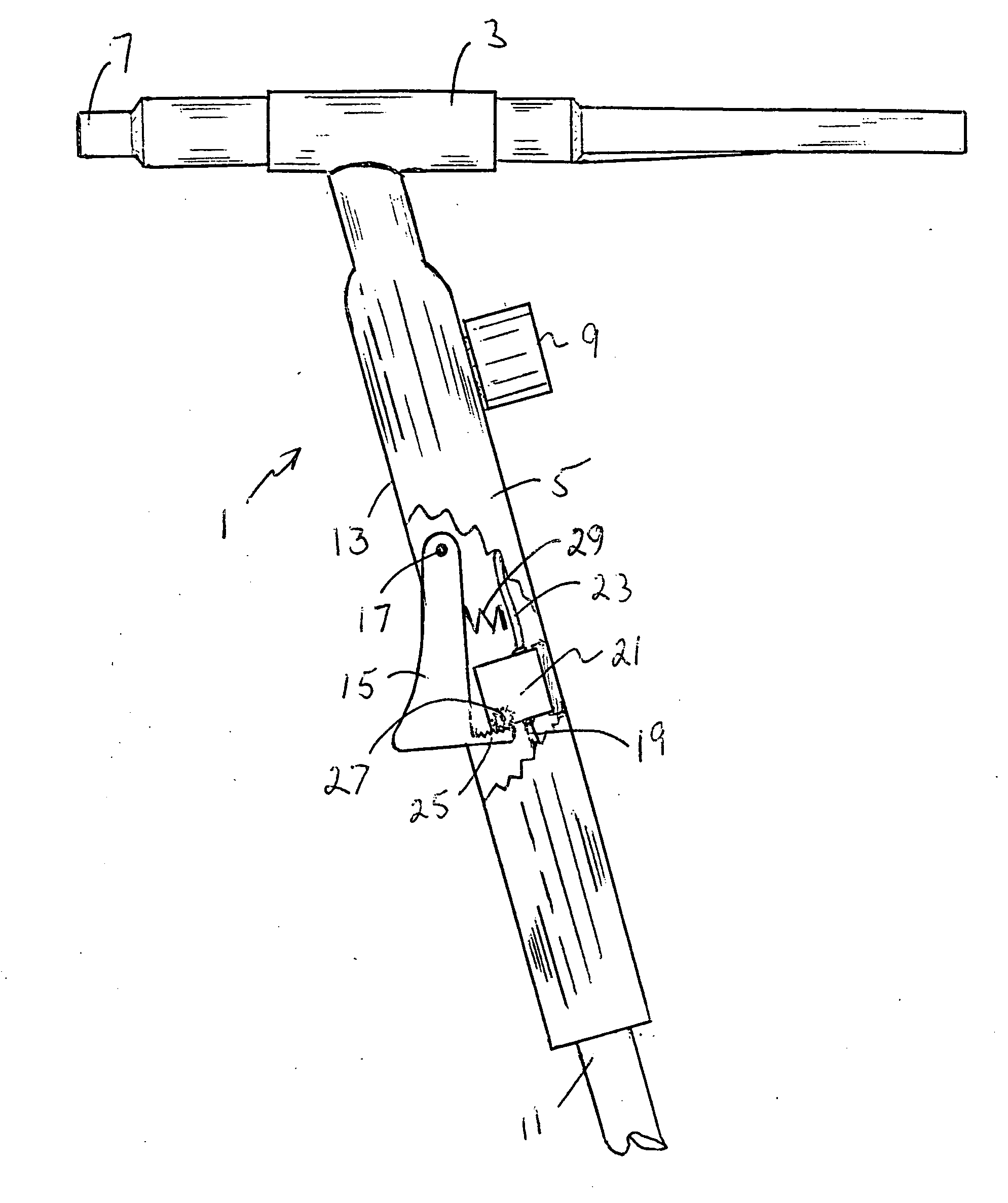
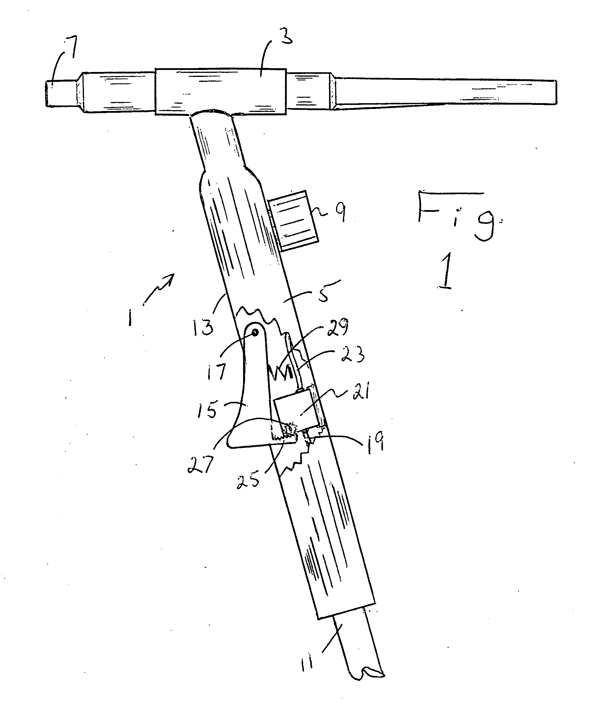
[0025] Referring now in detail to the drawings, FIG. 1 shows a side, partially cut view of present invention torch 1. Welder torch 1 includes a handle 5 with a discharge barrel 3 connected thereto at an obtuse angle of about 110°. The discharge barrel 3 has a front end which is an outlet end 7. There is an inert gas control knob 9 located on handle 5, and an inlet tube 11 entering the bottom of handle 5. Inlet tube 11 may contain separate inlet lines for electrical power and inert gas or water lines for liquid cooled torch. These arrangements are well known to the artisan and the details are a matter of choice. In normal torches, the power line would run through the handle 5 and to the discharge barrel outlet end 7. In the present invention torch, lower end 19 of the power line and upper end 23 of the power line are separated by a rotary potentiometer in housing 21. Trigger 15 controls the power passing through the potentiometer in housing 21. Trigger 15 is hingedly connected to han...


PUM

PropertyMeasurementUnit
angleaaaaaaaaaa
obtuse angleaaaaaaaaaa
angleaaaaaaaaaa

Abstract

The present invention welding torch includes a holdable torch gun having a first connection for hook up to a gas or water supply, and a second connection for hook up to a power supply. The gun has a discharge barrel with an outlet end, and a handle extending downwardly from the discharge barrel. The discharge barrel has a front facing in a same direction as the outlet end of the discharge barrel. The handle has a variable power trigger located thereon such that the trigger is spring loaded away from the handle and may be moved by pressure toward the handle, the trigger having an unsqueezed position and a fully squeezed position and a range of motion area between the unsqueezed position and the fully squeezed position. The handle also has an amperage control mechanism located therein and connected to the second connection. The trigger is moveably connected to the amperage control mechanism such that the unsqueezed position prevents any current to flow to the discharge barrel, the fully squeezed position permits maximum current to flow to the discharge barrel and any squeezed portion therebetween permits a proportionate amount of current to flow to the discharge barrel in proportion to distance between the unsqueezed position and the fully squeezed position. The welding torch amperage control mechanism may be a linear potentiometer or the trigger may include a rack gear functionally connected to a geared rotary potentiometer.

Description

BACKGROUND OF THE INVENTION [0001] 1. Field of the Invention [0002] The present invention relates to welding torches that have improved, ergonomic, handle based, amperage control mechanisms. These mechanisms are convenient, ergonomic and efficient due to their trigger operated arrangements. [0003] 2. Information Disclosure Statement [0004] The following patents relate to welding torches: [0005] U.S. Pat. No. 3,968,341 describes a welding torch handle including electrical control means thus enabling a welder, by the control on the handle, to vary the welding current supplied to an electrode in the torch head fitted to the handle. The handle is characterized by employing a linearly actuated control that can continuously vary current applied to the electrode from 0 amps to the full setting on the welding power supply. This control eliminates foot, hand held, or motor driven controls and provides convenient single-handed current control by the welder. [0006] U.S. Pat. No. 4,051,344 desc...

Claims


Application Information

Patent Timeline
Patent Type & Authority Applications(United States)
IPC IPC(8): B23K9/29
CPCB23K9/295
Inventor BLIDE, DANIEL J.
Owner BLIDE DANIEL J
Why Eureka
Try Eureka