Warewashing chemical dispenser

Inactive Publication Date: 2005-02-03
WELCO
View PDF7 Cites 36 Cited by
  • Summary
  • Abstract
  • Description
  • Claims
  • Application Information

AI Technical Summary

Benefits of technology

[0022] Main object of the invention reside in enabling a vacuum breaker to stably operate even at low pressures, making individual systems and parts, which constitute

Problems solved by technology

Also, there is a problem that lightening of the valve disc 41 increases the possibility that the valve disc 41 does not fall, with the result that the air hole 37 remains close to be unable to form an air layer, so that the vacuum breaker 17 is made inoperative.
Accordingly, there is caused a problem that piping becomes complex and there is a need of a space for a piping work.
In recent years, however, there are caused problems that since the detergent container 15 is lightened and manufactured to be thin-walled, the container mounting and dismounting safety cut-off valve lever 14a bites into the detergent container

Method used


Image

  • Warewashing chemical dispenser
  • Warewashing chemical dispenser
  • Warewashing chemical dispenser

Examples


first embodiment

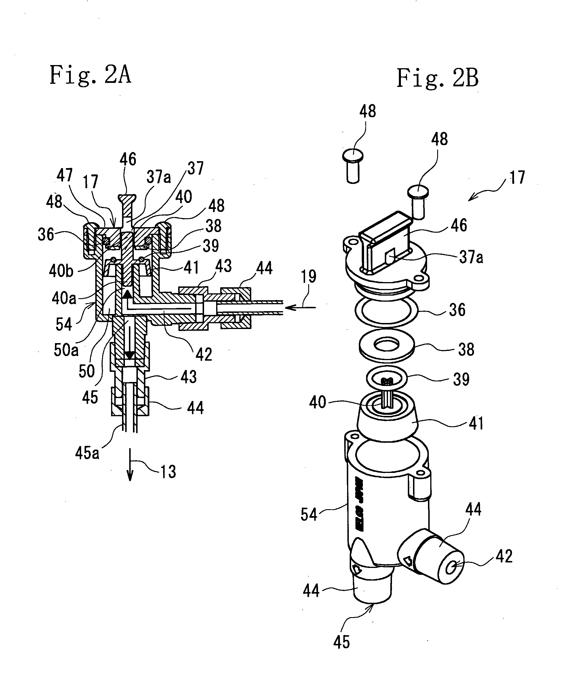
[0051] First, a vacuum breaker according to a first embodiment (claim 1) of the invention will be described with reference to FIGS. 2 and 3.

[0052] A vacuum breaker 17 according to the invention comprises an inlet path 42 and an outlet path 45, a cap.47 mounts a plate-shaped packing 38 on a lower end surface thereof, a valve disc 41 is provided on a vertical support shaft 40 inserted into an air hole 37 of the cap 47, and the valve disc 41 is moved up and down to be able to open and close the air hole 37.

[0053] Provided in an inner chamber 50 in a casing 54 of the vacuum breaker 17 is an inlet passage 50a to make the inlet path 42 substantially perpendicular to the outlet path 45 so as to permit flow of hot water to fountain perpendicular upward. Also, a vertical support shaft lower portion 40a is extended downwardly of the vertical support shaft 40 of the valve disc 41 so that the valve disc 41 can be stably operated even at low pressures, and a vertical support shaft upper portio...

second embodiment

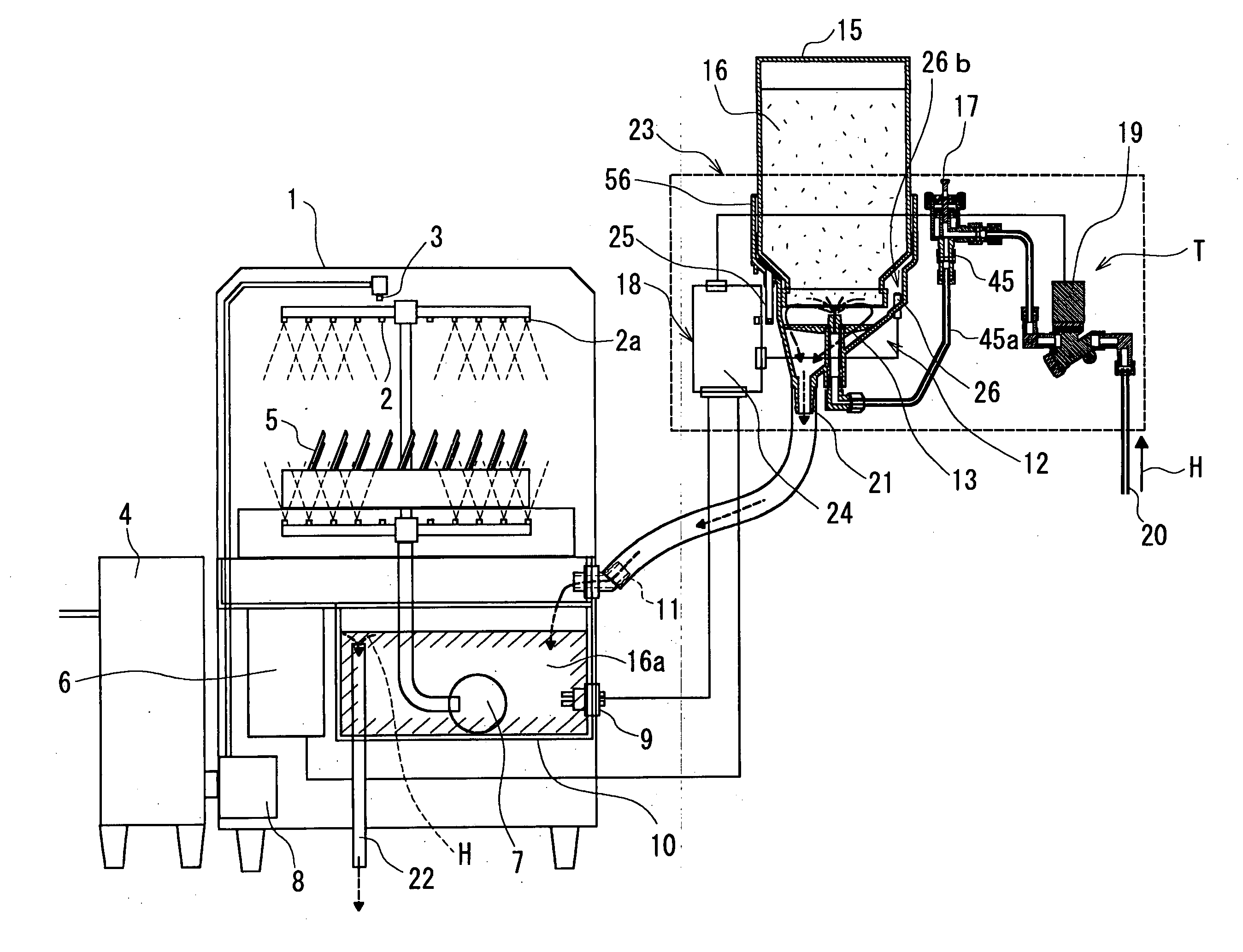
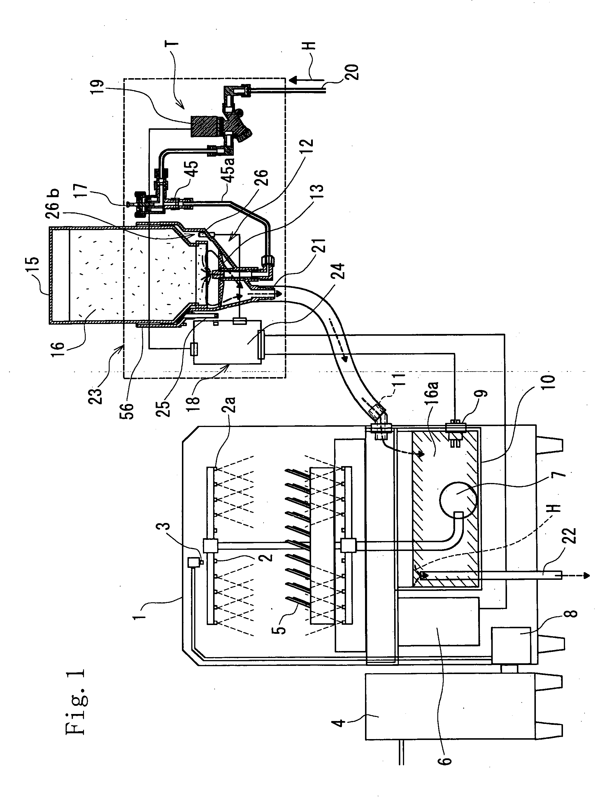
[0060] A warewashing chemical dispenser 23 according to a second embodiment (claim 2) of the invention is described with reference to FIGS. 4, 5 and 6.

[0061] The warewashing chemical dispenser 23 according to the second embodiment of the invention serves to store equipments, which constitute the warewashing chemical dispenser 23 and for which piping and wiring are necessary, compactly in the warewashing chemical dispenser 23.

[0062] The warewashing chemical dispenser comprises a detergent dissolving system having a detergent dissolving nozzle 13 substantially centrally thereof, the detergent dissolving nozzle 13 being arranged substantially centrally of a container receiving part 56, and a solution outlet 21 is arranged offset from the center of the container receiving part 56, a storage section T being formed in the warewashing chemical dispenser 23.

[0063] And received in the storage section T in the vicinity of the container receiving part 56 is a hot water control solenoid valv...

third embodiment

[0064] A container mounting and dismounting safety cut-off mechanism 25 in the warewashing chemical dispenser 23 according to a third embodiment (claim 3) of the invention will be described with reference to FIGS. 8 and 9.

[0065] With the container mounting and dismounting safety cut-off mechanism 25 of a detergent dissolving system in the warewashing chemical dispenser according to the third embodiment of the invention, a container bearing part 56a having substantially the same inclination as that of an inclined shoulder of a detergent container 15 is provided in a lower portion of the container receiving part 56, and the container bearing part 56a comprises a rod 27a mounting at a lower end thereof a magnet 28 and connected to a lower portion of a vertically moving shaft 25a provided at an upper end thereof with an inclination portion 25b corresponding to the inclined shoulder of the detergent container 15, and a coil spring 27 provided on the rod 27a to make the vertically moving...


PUM

PropertyMeasurementUnit
Pressureaaaaaaaaaa

Abstract

The invention relates to a warewashing chemical dispenser, enables a vacuum breaker to stably operate even at low pressures, makes individual systems and parts, which constitute a warewashing chemical dispenser, compact, and enables mounting of a container mounting and dismounting safety cut-off mechanism and an overflow preventive mechanism. A vacuum breaker for warewashing chemical dispensers, including an inlet path, an outlet path, a plate-shaped packing mounted on a lower end surface of a cap, and a valve disc provided on a vertical support shaft inserted through an air hole of the cap, the valve disc being moved up and down to be able to open and close the air hole, the vacuum breaker comprising an inlet passage provided in an inner chamber of a casing to form the inlet path substantially perpendicular to the outlet path, a vertical support shaft upper portion extended downwardly of a vertical support shaft of the valve disc, a vertical support shaft lower portion of the vertical support shaft formed to have a small diameter, a second O-ring mounted on an upper surface of the valve disc, the plate-shaped packing being mounted on a bottom surface of the cap opposed to the upper surface of the valve disc, and a cap dismounting lever provided centrally of an upper surface of the cap.

Description

BACKGROUND OF THE INVENTION [0001] 1. Field of the Invention [0002] The present invention relates to a warewashing chemical dispenser for performing concentration control of detergent of solid, powder, granulated powder or the like. [0003] 2. Background Art [0004] As conventional warewashing chemical dispensers, Japanese Patent No. 3145918 discloses arrangements of detergent dissolving units, detergent feed control systems, vacuum breakers, hot water control solenoid valves, or the like by means of wiring and piping work. [0005] Detergents for automatic dish washers, food container washers, and plate washers are classified into liquid, solid, granulated powder and powder, and liquid among them is easy to feed with the use of a liquid pump while the mainstream for detergent of solid, granulated powder and powder resides in a method shown in FIG. 13, in which a system for feeding them after dissolution is constituted. [0006] In FIG. 13, when an automatic dishwasher start to operate, h...

Claims


Application Information

Patent Timeline
IPC IPC(8): A47L15/44
CPCB01F1/0027A47L15/4436B01F21/22
Inventor KON, YUKIOONO, KENICHI
Owner WELCO
Why Eureka
Try Eureka