Air bag system

a technology of airbag system and air bag, which is applied in the direction of bicycle equipment, pedestrian/occupant safety arrangement, vehicle components, etc., can solve the problems of increased size, difficult mounting of airbag system to steering handlebar, and increased vibration resistance, so as to improve the effect of vibration resistan

Active Publication Date: 2005-02-03
HONDA MOTOR CO LTD
View PDF10 Cites 24 Cited by
  • Summary
  • Abstract
  • Description
  • Claims
  • Application Information

AI Technical Summary

Benefits of technology

[0009] It is accordingly an object of the present invention to provide an air bag system which can be suitably mounted on a two-wheeled or three-wheeled motorcycle by improving vibration resistance without causing an increase in size or other complications.

Problems solved by technology

In a two-wheeled or three-wheeled motorcycle, it is not easy to mount an air bag system to a steering handlebar as compared to a steering wheel.
The installation space for the air bag system is limited as compared with a four-wheeled vehicle.
However, increasing the vibration resistance of the inflator causes a size increase and a complication with respect to the inflator or a supporting member for the inflator.
As a result, this air bag system is not suitable for a two-wheeled or three-wheeled motorcycle.

Method used


Image

  • Air bag system
  • Air bag system
  • Air bag system

Examples


Embodiment Construction

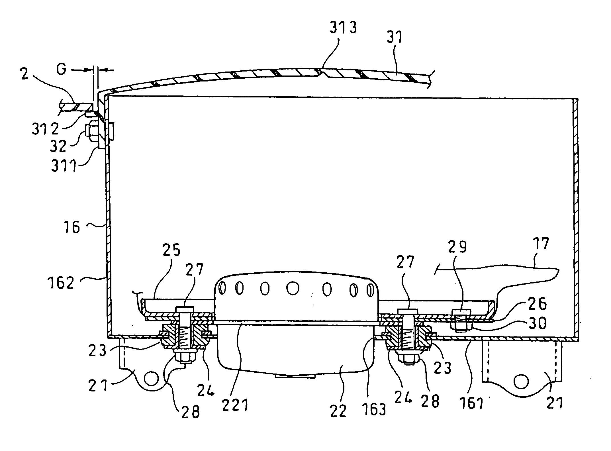
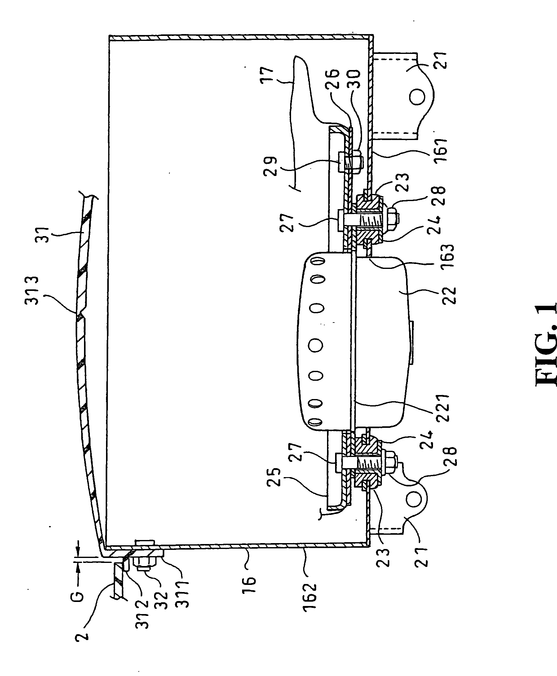
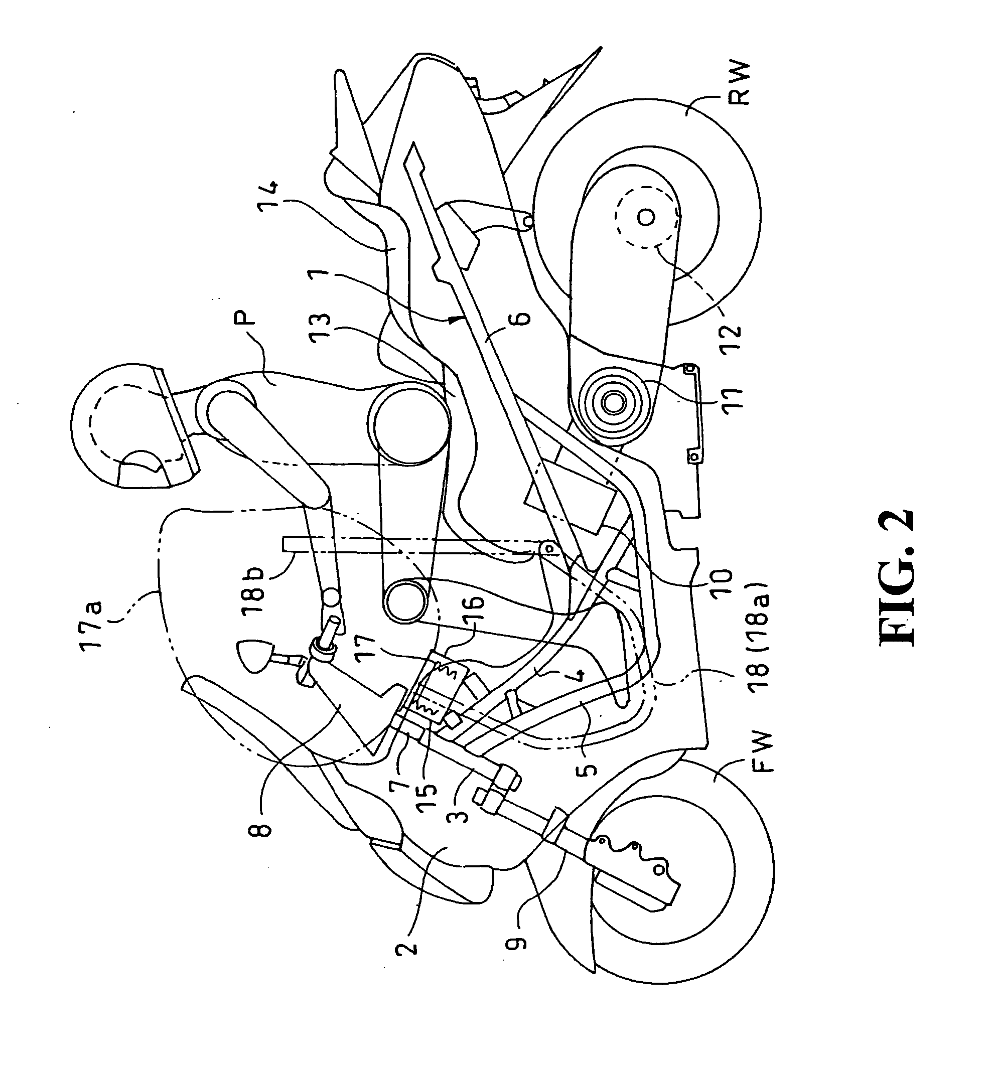
[0025] The present invention will now be described in detail with reference to the drawings. FIG. 2 is a side view of a motorcycle having an air bag system according to a preferred embodiment of the present invention. As shown in FIG. 2, the motorcycle includes a body frame 1 and a cowl 2 for covering the body frame 1. The cowl 2 is shown transparently as only a schematic outline for the purpose of understanding an essential part of the present invention. The body frame 1 is composed of a substantially upright head pipe 3 located at a front portion of the vehicle, a pair of right and left upper frames 4 welded at their front ends to the head pipe 3 and extending rearwardly, a pair of right and left lower frames 5 welded at their front ends to the head pipe 3 and extending downwardly and rearwardly, and a rear frame 6 joined to the upper frames 4 and the lower frames 5 and extending rearwardly.

[0026] A steering shaft 7 is inserted through the head pipe 3. A steering handlebar 8 is c...


PUM


Abstract

To suppress the transmission of vibrations from a vehicle body and an engine to an inflator in an air bag system. Rubber mounts are fitted to a retainer box for accommodating an air bag. A flange of an inflator is placed on the rubber mounts, and bolts are inserted through set plates for connecting the air bag to the inflator and through the flange. The bolts are further inserted through the rubber mounts and nuts are tightened to the bolts.

Description

CROSS-REFERENCE TO RELATED APPLICATIONS [0001] The present application claims priority under 35 USC 119 to Japanese Patent Application No. 2003-140276 filed on May 19, 2003 the entire contents thereof is hereby incorporated by reference. BACKGROUND OF THE INVENTION [0002] 1. Field of the Invention [0003] The present invention relates to an air bag system, and more particularly to an air bag system having a structure capable of suppressing transmission of vibrations from a vehicle body and an engine to an inflator. [0004] 2. Description of Background Art [0005] An air bag system includes an air bag adapted to be developed between an occupant and a vehicle body to thereby prevent direct transmission of impact exerted on the vehicle to the occupant and an inflator for inflating the air bag. An air bag system mounted on a steering wheel of a vehicle is disclosed in Japanese Utility Model Laid-open No. Hei 5-76911. This conventional air bag system includes an inflator and a base plate fo...

Claims


Application Information

Patent Timeline
Patent Type & Authority Applications(United States)
IPC IPC(8): B60R21/20B60R21/203B60R21/217B62J27/00
CPCB60R21/2037B62J27/00B60R21/217B62J27/20
Inventor KUROE, TAKESHIHORIUCHI, TADANORIIIJIMA, SATOSHI
Owner HONDA MOTOR CO LTD
Why Eureka
Try Eureka