Automotive vehicle air bag system

Inactive Publication Date: 2005-02-03
GM GLOBAL TECH OPERATIONS LLC
View PDF12 Cites 51 Cited by
  • Summary
  • Abstract
  • Description
  • Claims
  • Application Information

AI Technical Summary

Benefits of technology

[0005] The present invention is for a vehicle having an air bag system for impact restraint. The air bag system provides protection to an occupant in the event of a collision by deploying an air bag in the space between the occupant seat and the vehicle interior components adjacent to the occupant.

Problems solved by technology

Air bag packaging is a continuing challenge.

Method used


Image

  • Automotive vehicle air bag system
  • Automotive vehicle air bag system
  • Automotive vehicle air bag system

Examples


second embodiment

[0063] a dual depth mechanism 130 will now be described in which the dual depth mechanism is integral with the plenum.

[0064] Referring to FIG. 8, the plenum 28 includes an inflation gas portion 132 having an inflation gas passage 134 to fluidly connect the primary inflator 26 to the fill end 44 of the fill tube 30. The plenum 28 also includes a generally tubular piston housing portion 136, having a piston chamber 138 arranged approximately parallel to the inflation gas passage 134 and defined by a shared intermediate wall 140 and an exterior wall 142. The plenum 28 includes a pair of diametrically opposed vents with a first vent 144 in the intermediate wall 140 fluidly connecting the inflation gas passage 134 and the piston chamber 138 and a second vent 146 in the exterior wall 142 fluidly connecting the piston chamber 138 to atmosphere. The plenum may be cast or molded.

[0065] The plenum 28 defines, and may also be referred to as, a dual depth mechanism housing including a canister...

third embodiment

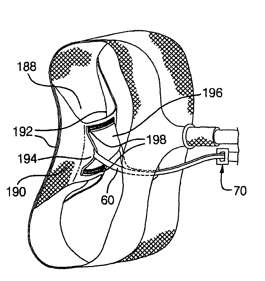
[0073] a dual depth mechanism 300 shown in FIGS. 21A-C will now be discussed. FIG. 21A shows a fill tube 30 with a dual depth mechanism 300 secured along the length of the fill tube 30. An L-shaped piston housing 301 contains a piston 302 that is retained in place by a retention member 304 which, in this case, is a pin, nested in a retention slot 305 formed in the piston 302. When the piston is in a non-actuated state, as shown in FIG. 21A, a fill tube vent 303 is in fluid communication with diametrically opposed vents 306, 307 and vent 311 in the housing 301. The piston 302 has a stud portion 308 that protrudes through hole 309 in the housing 301 around which an air bag cushion external tether loop 68 is mounted. One or more tether loops 68 may be routed around the stud portion 308. An extension 312 is located adjacent to the housing 301 and formed with first and second extension openings 314, 316, respectively. The piston stud portion 308 rests within openings 314, 316 in the exte...

fourth embodiment

[0077] a dual depth mechanism 342 is shown in FIGS. 22A-C. In FIG. 22A, a “T” shaped piston housing 343 is shown (as opposed to “L” shaped as in the housing 301 shown in FIG. 21A). A piston 344 having a stud portion 346 is held in the housing 343. A stud end plug 348 blocks a stud end 350 of the housing 343 where the stud portion 346 protrudes. An extension 370 is attached to the fill tube. The extension 370 is configured to receive the stud portion 346 when the piston 344 is in the non-actuated position. Thus, when the tether loop 68 is placed around the stud portion 346 and the stud portion is then placed in the extension 370, the tether is retained on the stud. An optimal extension support 372 may be used to provide a smooth surface for the tether 68 to interact against.

[0078] An actuator 352 is held in an actuator holder 354. The actuator holder 354 is crimped in the housing 343. A piston chamber 356 is formed in the housing 343 and is bounded by the piston 344, the plug 348, th...


PUM


Abstract

The present invention is for a vehicle having an air bag system for impact restraint. The air bag system includes a gas emitting inflator for emitting inflation gas upon receiving a signal of an impact, a fill tube having a fill end in fluid communication with the inflator to port the inflation gas from the inflator, and an air bag cushion in fluid communication with the fill tube to receive the inflation gas from the fill tube and deployable in an interior space adjacent to a seat upon the impact. The air bag system also includes a tether operable to both a restricted and unrestricted length in conjunction with a dual depth mechanism. The air bag system may further include a vent operable to both an open and a closed state in conjunction with the dual depth mechanism.

Description

TECHNICAL FIELD [0001] The present invention is for an air bag system installed in an automotive vehicle. BACKGROUND OF THE INVENTION [0002] Air bags are a known safety device installed in vehicles today. For supplemental occupant protection during a collision, air bags may be used. Air bag packaging is a continuing challenge. The need to position the air bag such that it will be deployable in the desired space must be reconciled with spatial constraints imposed by other vehicle componentry. For instance, frontal air bags are traditionally installed in the hub of the steering wheel for the driver and in a recess of the instrument panel for the front seat passenger. This allows the air bags to fill the space between the passenger and the front interior of the vehicle upon deployment in a frontal collision. [0003] Frontal passenger air bag modules are relatively large and may drive larger than desired instrument panels from an interior volume stand point. Vehicle designers are explori...

Claims


Application Information

Patent Timeline
Patent Type & Authority Applications(United States)
IPC IPC(8): B60R21/16B60R21/20B60R21/21B60R21/213B60R21/217B60R21/231B60R21/233B60R21/26
CPCB60R21/21B60R21/213B60R21/2171B60R21/23138B60R2021/2612B60R21/2338B60R2021/161B60R2021/23386B60R21/233
Inventor THOMAS, SCOTT DAVID
Owner GM GLOBAL TECH OPERATIONS LLC
Why Eureka
Try Eureka