Plasma display panel

a technology of display panel and plasma, which is applied in the direction of gas-filled discharge tube, gas discharge sealing, and electrode insertion, etc., can solve the problems of increasing the likelihood of production defects, complex process involved in forming electrodes, and increasing so as to reduce the pitch of electrodes and facilitate the connection between electrodes and connecting elements in the terminal region

Inactive Publication Date: 2005-02-03
SAMSUNG SDI CO LTD
View PDF2 Cites 6 Cited by
  • Summary
  • Abstract
  • Description
  • Claims
  • Application Information

AI Technical Summary

Benefits of technology

[0014] In one exemplary embodiment of the present invention, there is provided a plasma display panel in which connection between electrodes and connecting elements in a terminal region is made easy without reducing a pitch of electrodes in the terminal region.

Problems solved by technology

However, a drawback of such a configuration of the conventional PDP is that the processes involved in forming the electrodes are made complicated by minimizing the distance between scanning electrodes 1 in terminal region 7.
The small distance between scanning electrodes 1 also increases the likelihood that there will be production defects.
These problems are of particular concern in PDPs realized using fine pitch panels.

Method used


Image

  • Plasma display panel
  • Plasma display panel
  • Plasma display panel

Examples


Embodiment Construction

[0023] An exemplary embodiment of the present invention will now be described in detail with reference to the accompanying drawings.

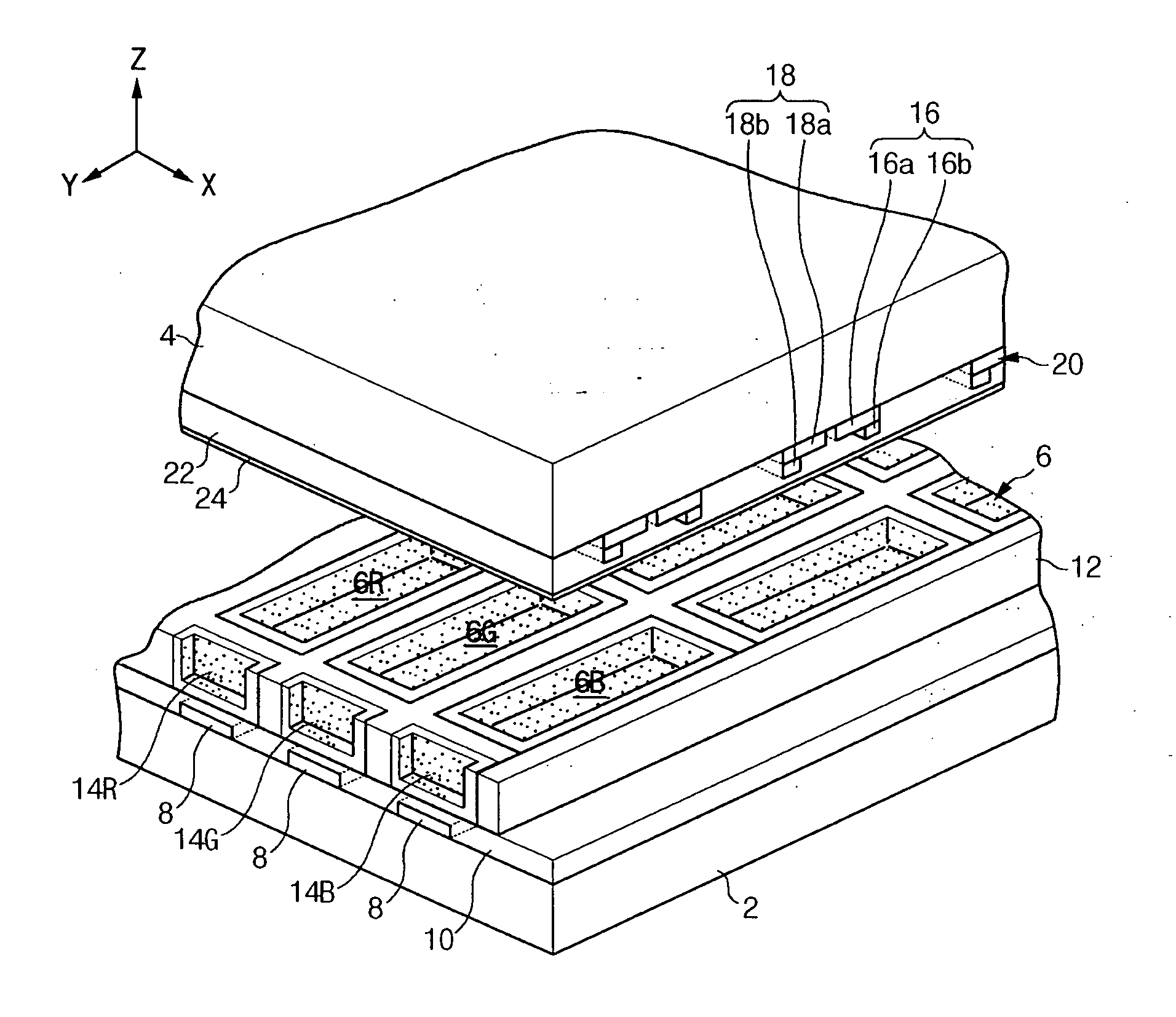
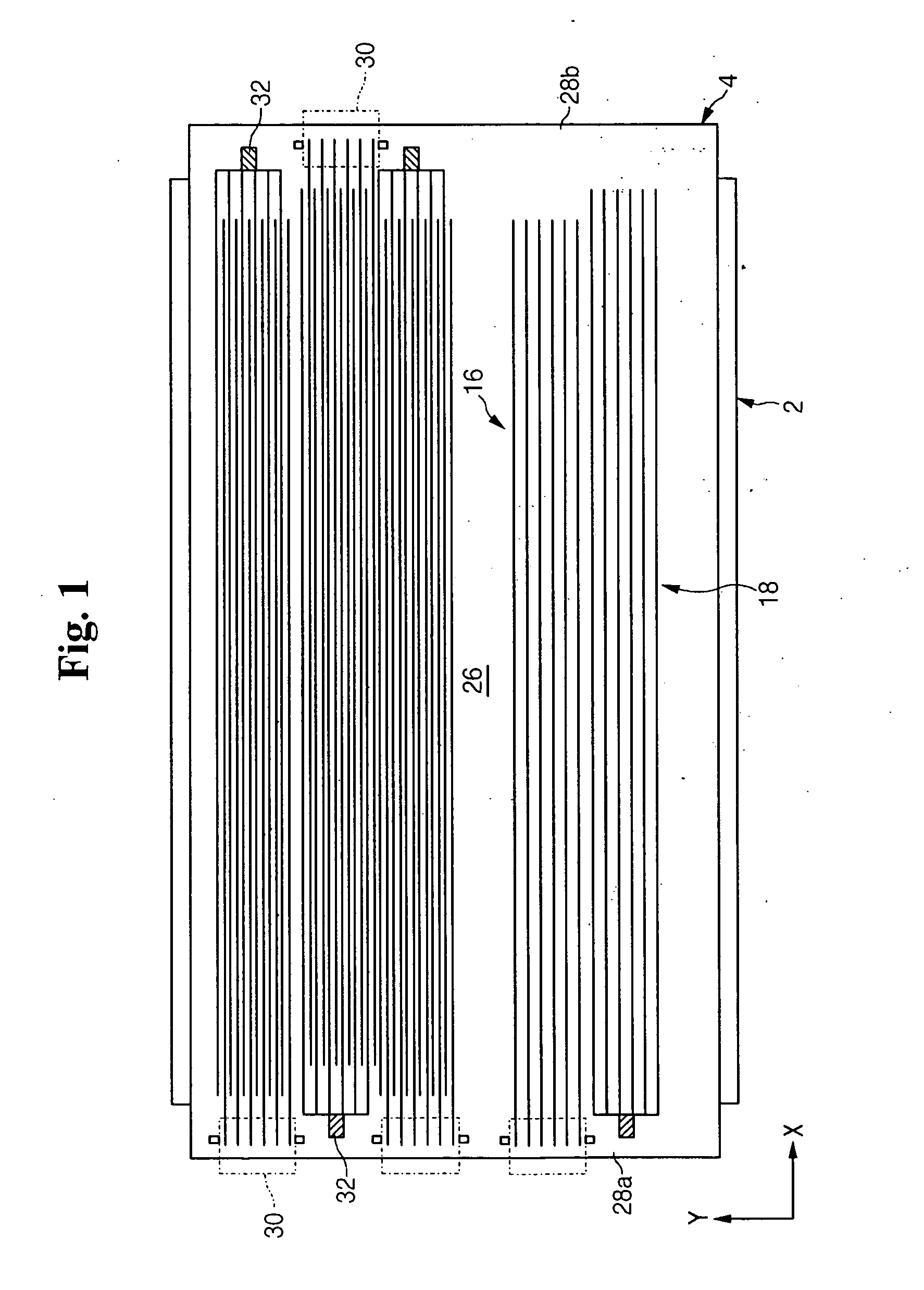
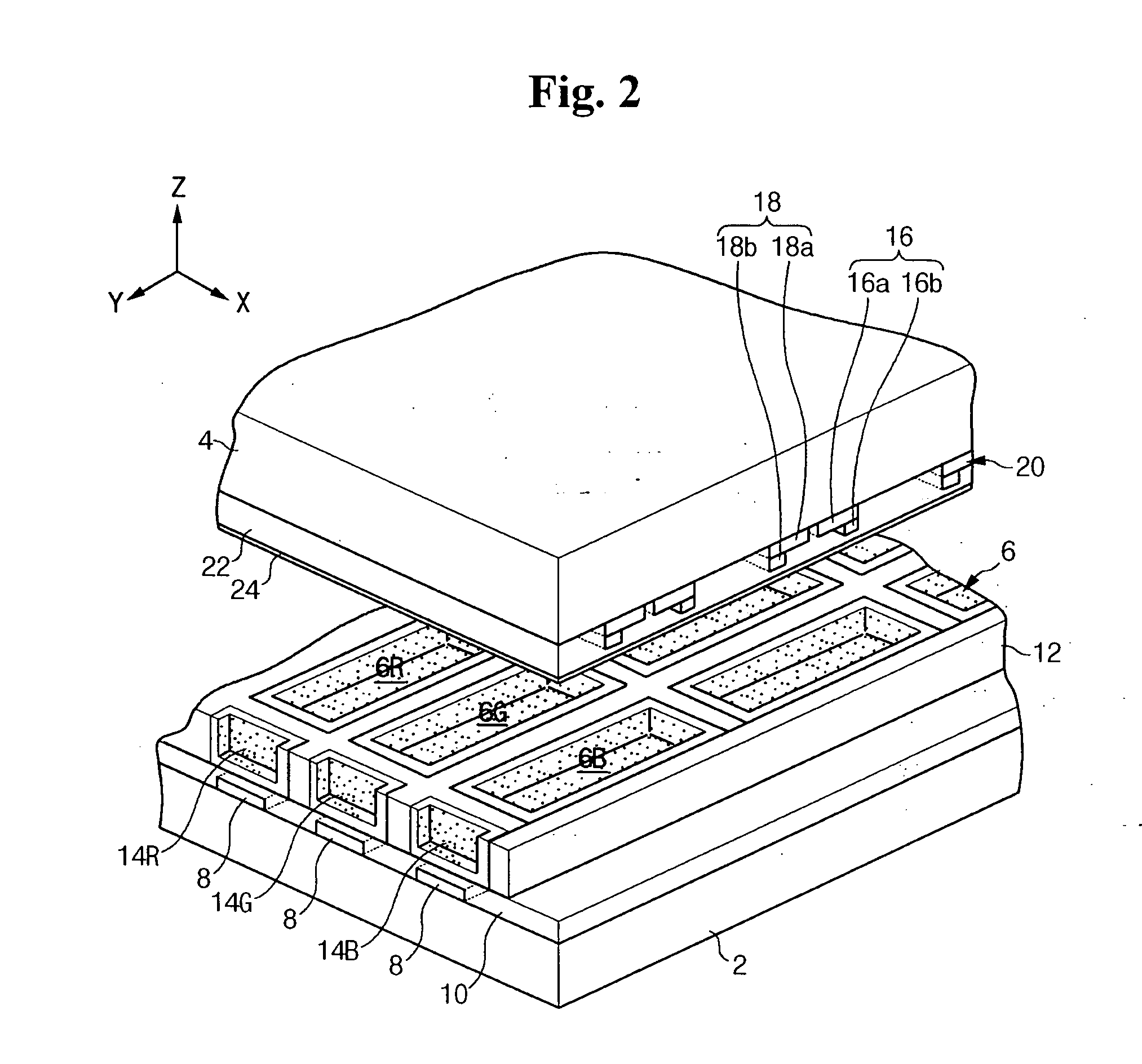
[0024] With reference to FIGS. 1 and 2, the plasma display panel (PDP) according to an exemplary embodiment of the present invention includes first substrate (or rear substrate) 2 and second substrate (or front substrate) 4. Substrates 2 and 4 are formed in a substantially rectangular shape having long sides and short sides. Hence, the substrates 2 and 4 are defined by long side edges and short side edge. First substrate 2 and second substrate 4 oppose one another and are substantially parallel to one another. Also, substrates 2 and 4 have a predetermined gap therebetween. Discharge cells 6R, 6G, and 6B are formed in the gap between first and second substrates 2 and 4, and visible light for displaying color images is emitted by the independent discharge mechanisms of each of the discharge cells 6R, 6G, and 6B.

[0025] In more detail, address electrodes ...


PUM


Abstract

A plasma display panel includes a first substrate and a second substrate opposing one another with a predetermined gap therebetween. Address electrodes are formed on the first substrate. Also, barrier ribs are mounted in the gap between the first substrate and the second substrate, and define discharge cells in a predetermined display region of the first and second substrates. Phosphor layers are formed in the discharge cells. Further, scanning electrodes and display electrodes are formed on the second substrate. The scanning electrodes and the display electrodes each have a pitch in the display region that is identical to a pitch in terminal regions, which are formed to the outside of the display region.

Description

CROSS-REFERENCE TO RELATED APPLICATIONS [0001] This application claims priority to and the benefit of Korean Patent Application No. 2003-0052597 filed on Jul. 30, 2003 in the Korean Intellectual Property Office, the entire content of which is incorporated herein by reference. BACKGROUND OF THE INVENTION [0002] (a) Field of the Invention [0003] The present invention relates to a plasma display panel (PDP), and more particularly, to an electrode structure of a PDP. [0004] (b) Description of the Related Art [0005] A PDP is a display device in which vacuum ultraviolet rays generated by the discharge of gas in discharge cells excite phosphors to realize predetermined images. As a result of the high resolution possible with PDPs (even with large screen sizes), this flat panel display configuration is quickly emerging as one of the most popular displays. [0006] Depending on how the PDP is driven, this display configuration is classified into the different types of the AC PDP, DC PDP, and c...

Claims


Application Information

Patent Timeline
Patent Type & Authority Applications(United States)
IPC IPC(8): H01J11/12H01J11/24H01J11/26H01J11/46H01J11/48
CPCH01J11/46H01J11/12H01J11/24
Inventor MOON, CHEOL-HEE
Owner SAMSUNG SDI CO LTD
Why Eureka
Try Eureka