Self-installing column stabilized offshore wind turbine system and method of installation

a self-installing, wind turbine technology, applied in the direction of wind energy generation, mechanical equipment, machines/engines, etc., can solve the problems of large installation cost of spar type floating structures, and inconvenient installation of fixed wind supporting structures in deepwater environments. , to achieve the effect of reducing the installation cost and time to develop wind farms, reducing wave excitation, and increasing hydrodynamic mass

Inactive Publication Date: 2018-10-02
SRINIVASAN NAGAN
View PDF12 Cites 20 Cited by
  • Summary
  • Abstract
  • Description
  • Claims
  • Application Information

AI Technical Summary

Benefits of technology

[0020]One of the significant features and advantages of the present invention is that the submersible platforms can fully assembled in their compact mode and the wind turbine may be mounted on the platform in a sheltered area near the quayside and the whole structure can be towed to a wind-farm located in the offshore deepwater by a tug boat that has anchor handling capability rather than expensive cranes or derricks mounted on offshore construction vessels, thereby significantly reducing the installation cost and time to develop wind farms.
[0021]Another feature and advantage of the present column stabilized semi-submersible platforms is that the telescoping keel tank or stiffened damper plate in the fully extended position during operation provides required stability to the horizontal and vertical wind turbine loads.
[0022]Another feature and advantage of the present column stabilized semi-submersible platforms is that the telescoping keel tank or damper plate in the fully extended position is distanced beneath the severe kinematics of wave particle motion, thereby significantly reducing wave excitation imparted to the supporting floating structure.
[0023]Another feature and advantage of the present column stabilized semi-submersible platforms is that the telescoping keel tank or damper plate provides water entrapment above and below the flat surfaces thereof, thereby increasing the hydrodynamic mass and flow damping to reduce the heave, pitch and roll motion of the supporting floating structure in the operational mode.
[0024]A further feature and advantage of the present column stabilized semi-submersible platforms is that the telescoping keel tank or damping plate may be used as a base to support the fabrication of the columns from bottom to top in a modular manner.
[0025]A still further feature and advantage of the present column stabilized semi-submersible platforms is that the telescoping keel tank or damping plate may be fully retracted to provide minimum height for the ease of wet transport towing of the platform or placement on the deck of a vessel for dry transport.

Problems solved by technology

Fixed wind supporting structures are not cost effective in deepwater locations.
Fixed wind supporting structures are not cost effective in the deepwater environment.
SPAR type floating structures require large installation cost.
Conventional column stabilized semi-submersible platforms are not suitable because of the requirement of large pontoons.
Tension leg platforms have several drawbacks which low vertical natural frequencies in the neighborhood of the service wave excitation, installation of the tendons, and onsite installation of the wind turbines, and the coupling behavior between the turbines and the tendons to the environmental and operational loads are significant.

Method used


Image

  • Self-installing column stabilized offshore wind turbine system and method of installation
  • Self-installing column stabilized offshore wind turbine system and method of installation
  • Self-installing column stabilized offshore wind turbine system and method of installation

Examples


Embodiment Construction

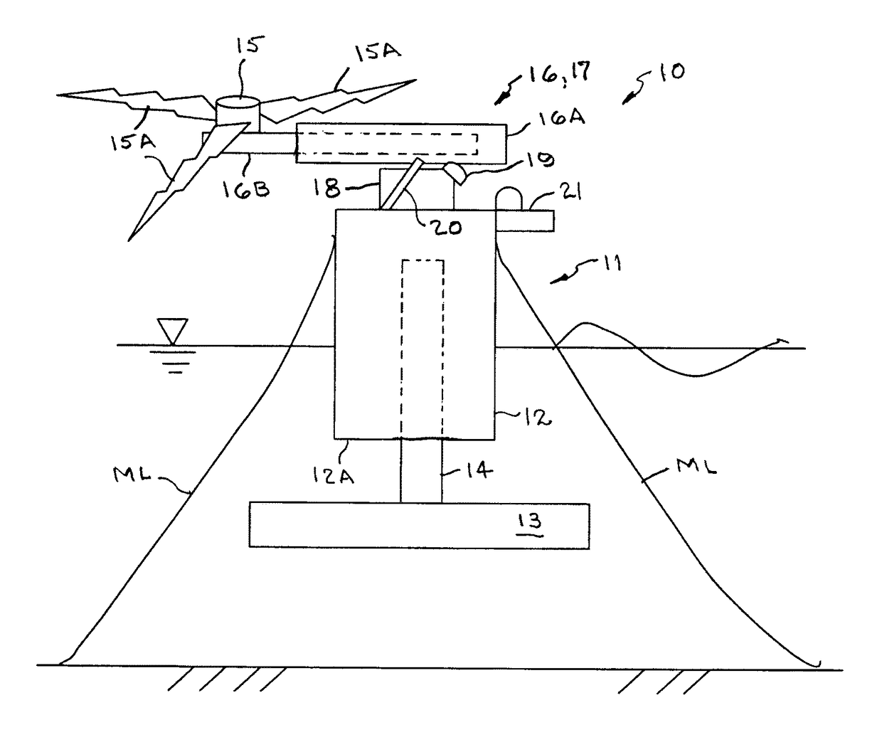
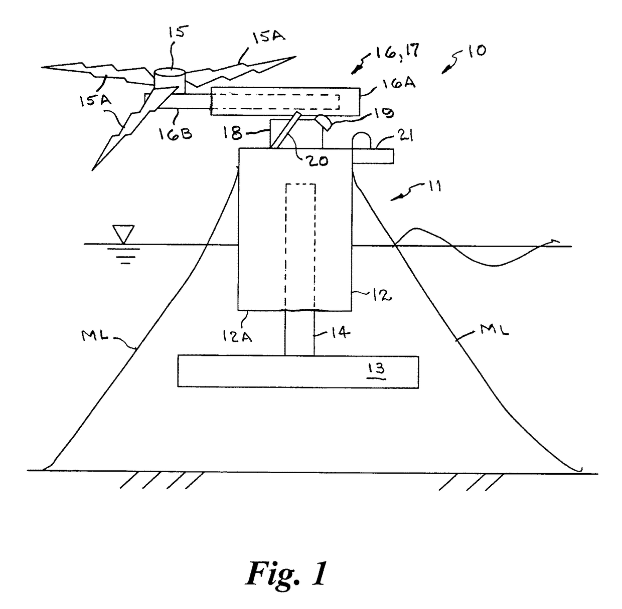
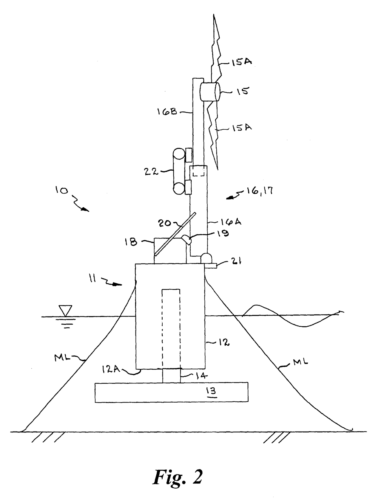
[0038]The term “column stabilized” as used in the mobile offshore drilling industry refers to a class of mobile offshore drilling units (MODU) wherein the static stability is obtained from the water plane area and the overall center of buoyancy (CB) is allowed to be below the overall center of gravity (CG) of the floating unit with its static loads. When the center of gravity (CG) of the overall platform is situated below the overall center of buoyancy (CB), then positive natural stability is obtained. The term “semi-submersible” as used in the mobile offshore drilling industry refers to a particular type of floating vessel that is supported primarily on large pontoon-like structures submerged below the sea surface and operating decks are elevated perhaps 100 or more feet above the pontoons on large steel columns. The semi-submersible has the advantage of submerging most of the area of components in contact with the sea and minimizing loading from waves and wind. Semi-submersible pl...


PUM


Abstract

A self-installing offshore column stabilized semi-submersible platform has at least one vertical buoyant ballastable column, a telescoping keel tank or stiffened damper plate movably connected with the vertical column that extends and retracts relative to a lower end thereof, and a non-collapsible turbine tower or a tilt and telescoping tower coupled to an upper end of the vertical column that telescopes and reciprocates relative thereto between a horizontal retracted position and an axially extended vertical position. A wind turbine with blades is coupled to a top portion of the tower assembly. The relative position and weight of the keel tank or damper plate is selectively adjustable to raise or lower the center of gravity of the entire mass of the semi-submersible platform including the wind turbine and tower assembly with respect to the center of buoyancy of the platform.

Description

BACKGROUND OF THE INVENTION1. Field of the Invention[0001]This invention relates generally to offshore wind turbines and methods of installation thereof and, more particularly, to a self-installing wind turbine system having a column stabilized semi-submersible platform with a telescoping keel tank or telescoping motion dampers and a tilt and telescoping wind turbine tower assembly or non-collapsible turbine tower, and method of installation thereof.2. Background Art[0002]Offshore wind energy is increasing in popularity. Most wind power farm development is in shallow water. In deep water, more distant from the shore, the wind resources are far superior to the near shore shallow water locations. Fixed wind supporting structures are not cost effective in deepwater locations. To harness these deepwater wind resources, wind turbines are mounted onto floating platforms. The industry typically modifies and downsizes conventional floating vessel technology developed for oil and gas deepwat...

Claims


Application Information

Patent Timeline
Patent Type & Authority Patents(United States)
IPC IPC(8): E04H12/18E04H12/34F03D13/10F03D9/00F03D13/20F03D13/25
CPCF03D11/045F03D13/25E04H12/345F03D9/00E04H12/187F03D13/20F03D13/10F05B2240/9151F05B2240/9152F05B2240/93F05B2240/95Y02E10/727E04H12/182F03D13/22Y02E10/72Y02E10/728
Inventor SRINIVASAN, NAGAN
Owner SRINIVASAN NAGAN
Why Eureka
Try Eureka