Driving device for stepping motor

a technology of stepping motor and driving device, which is applied in the direction of programme control, dynamo-electric converter control, instruments, etc., can solve the problems the inability of the rotor to rotate smoothly, so as to prevent the occurrence of erroneous detection of the zero point

Active Publication Date: 2005-02-03
YAZAKI CORP
View PDF11 Cites 16 Cited by
  • Summary
  • Abstract
  • Description
  • Claims
  • Application Information

AI Technical Summary

Benefits of technology

[0014] It is therefore an object of the present invention to provide a driving device of a stepping motor in which the occurrence of erroneous detection of the zero point can be prevented.

Problems solved by technology

However, in a vehicle on which a meter having the above stepping motor is mounted, by an erroneous signal generated by vibration or noise of the vehicle, an actual moving distance of an indicating needle of the meter, which is linked with the rotation of the stepping motor, becomes different from an original moving distance of the indicating needle of the meter.
In the above zero position detection processing, the following problems may be encountered.
Further, since the rotating speed of the rotor is changed, the rotor can not be rotated smoothly.
Accordingly, there is a possibility of the occurrence of erroneous detection of the zero point.

Method used


Image

  • Driving device for stepping motor
  • Driving device for stepping motor
  • Driving device for stepping motor

Examples


Embodiment Construction

[0047] Referring to the drawings, an embodiment of the present invention will be explained below.

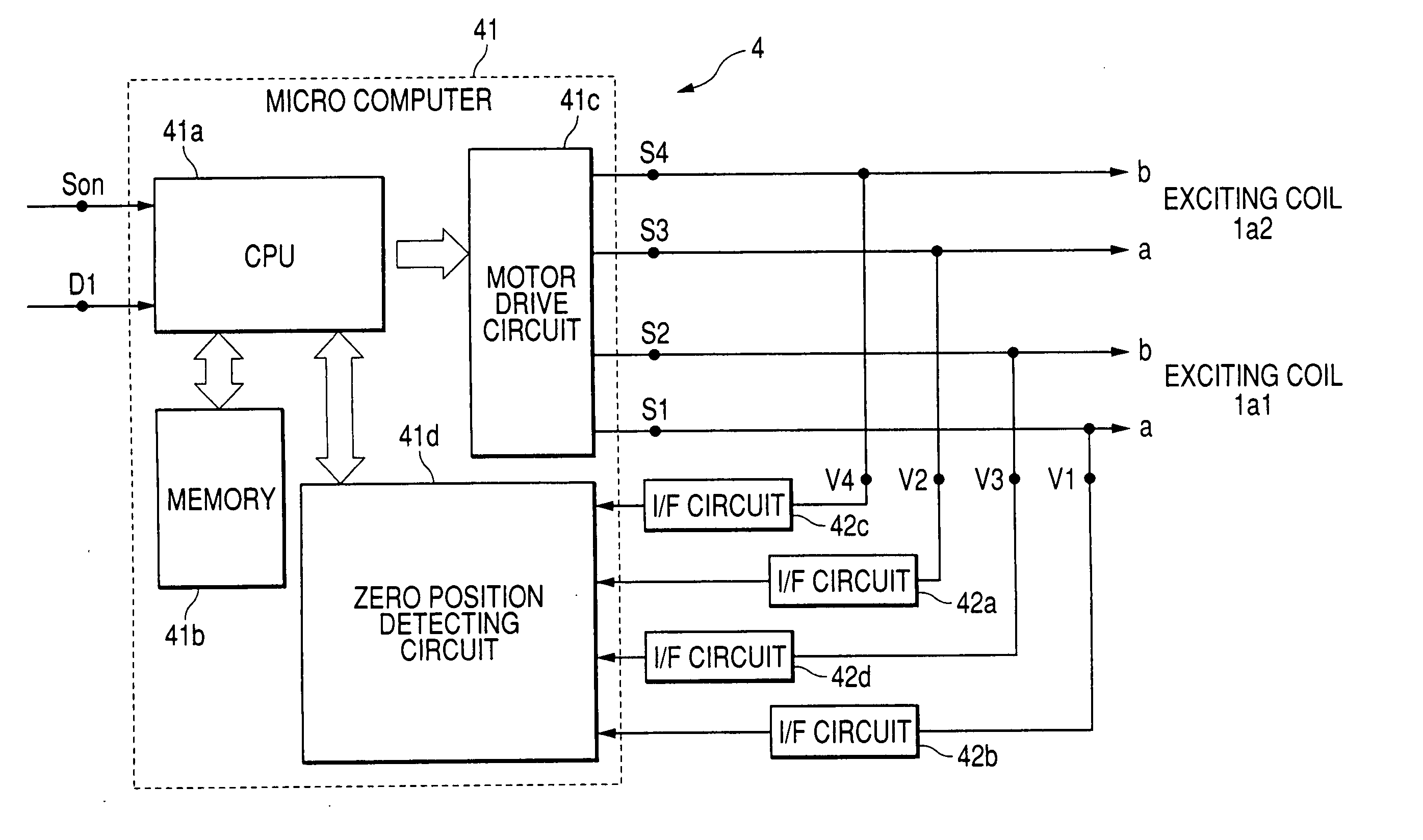
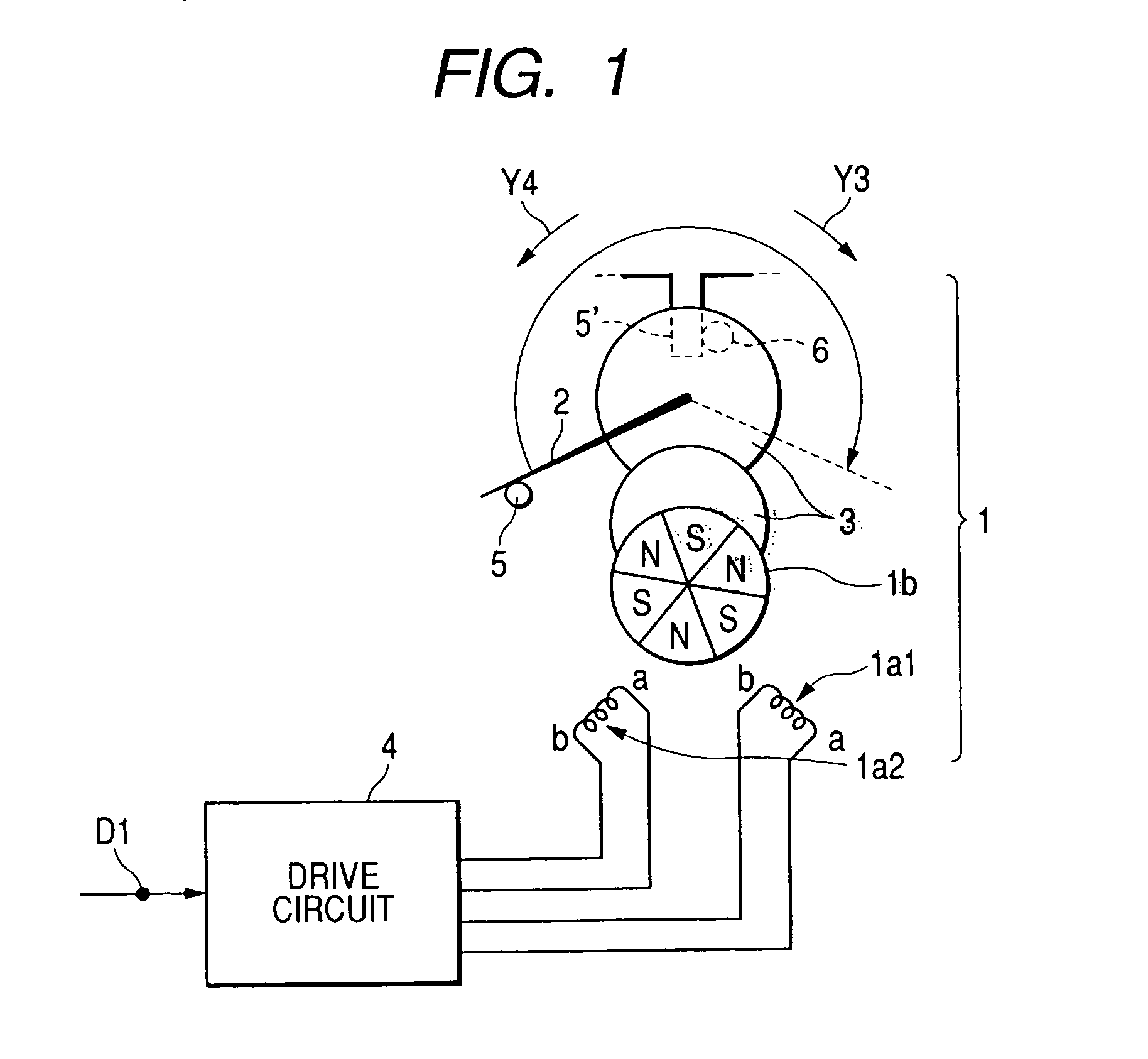
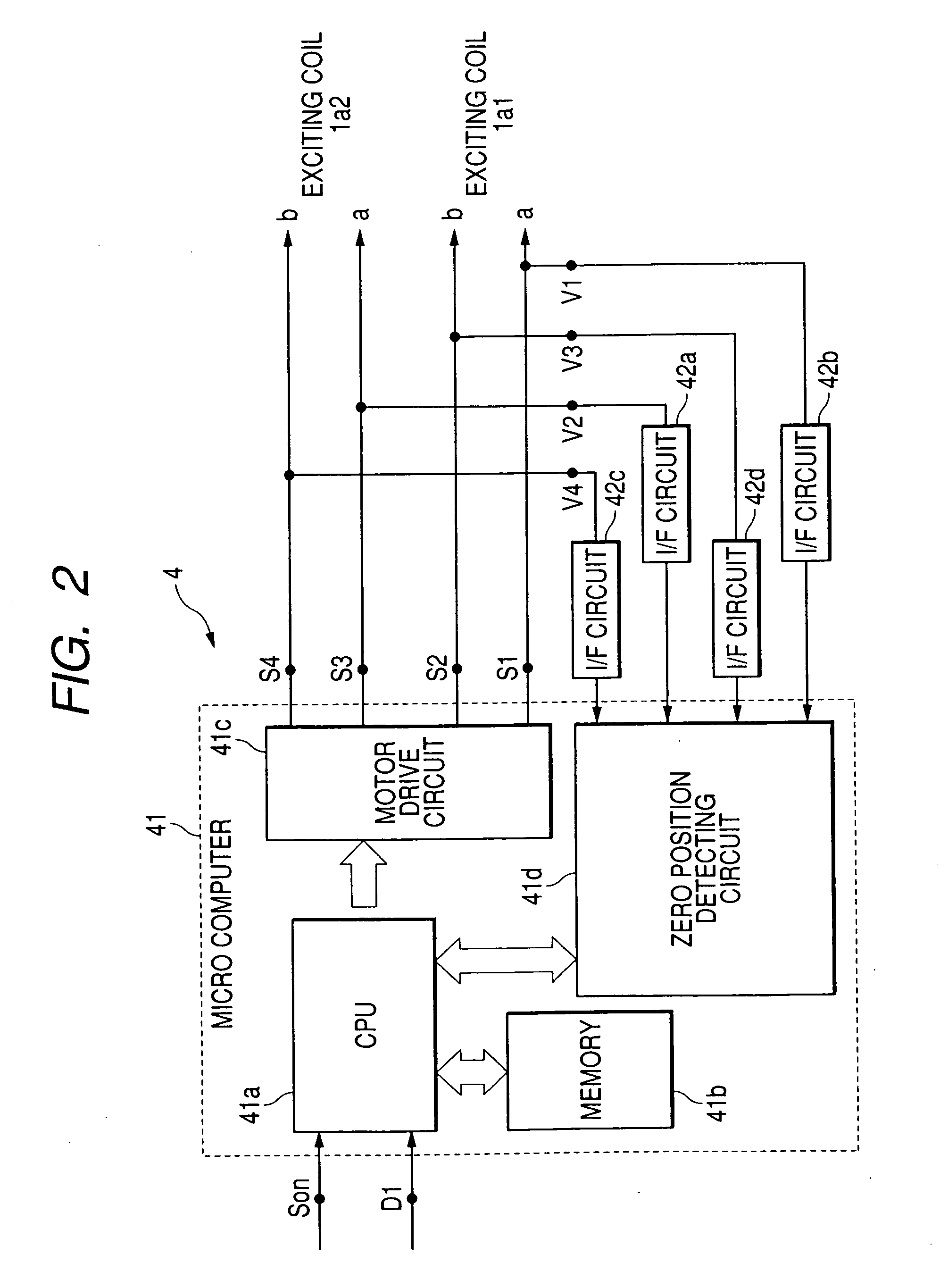
[0048]FIG. 1 is an arrangement view of the meter mounted on a vehicle to which the embodiment of the driving device of the stepping motor of the present invention is applied. The meter mounted on the vehicle is, for example, a speedometer. The meter mounted on the vehicle includes: a stepping motor 1 and a drive circuit 4 for controlling the drive of the stepping motor 1. The stepping motor 1 has two exciting coils 1a1, 1a2 arranged at positions making a right angle with a stator (not shown) and also has a rotor 1b in which three N-poles and S-poles are alternately magnetized. The rotor 1b is rotated in accordance with a change in the excitation of the exciting coils 1a1, 1a2.

[0049] The meter mounted on a vehicle further includes: an indicating needle 2, which is a member to be driven, engaged with the rotation of the rotor 1b; a gear 3 for transmitting the rotation of the rotor 1b to ...


PUM


Abstract

A driving device, includes a stepping motor having an exciting coil and a rotor; a driven member driven in accordance with a rotation of the rotor; a stopper mechanically stopping the driven member at a zero position; a controller controlling the state of excitation of the exciting coil; an induced voltage detector detecting an induced voltage generated by a change of magnetic flux according to the rotation of the rotor; and a zero position detector detecting a stoppage of the driven member at the zero position. The controller supplies an exciting pattern to the exciting coil at the time of processing of zero position detection. The exciting pattern includes a first exciting step for detecting the induced voltage and a second exciting step for rotation. Total periods of the first exciting step is greater than that of the second exciting step during an electrical angle 90° in the one cycle.

Description

BACKGROUND OF THE INVENTION [0001] The present invention relates to a driving device for a stepping motor. More particularly, the present invention relates to a driving device for a stepping motor, which is used for a meter mounted on a vehicle, the initialization processing of which is improved. [0002] Recently, stepping motors have been frequently used for speedometers to display a vehicle speed or for tachometers to display a rotating speed of an engine for the reasons of improving the indicating accuracy and reducing the manufacturing cost. [0003] However, in a vehicle on which a meter having the above stepping motor is mounted, by an erroneous signal generated by vibration or noise of the vehicle, an actual moving distance of an indicating needle of the meter, which is linked with the rotation of the stepping motor, becomes different from an original moving distance of the indicating needle of the meter. [0004] Therefore, in the case of the meter mounted on a vehicle in which t...

Claims


Application Information

Patent Timeline
Patent Type & Authority Applications(United States)
IPC IPC(8): H02P8/02H02P8/08H02P8/22
CPCH02P8/08H02P8/02
Inventor YAMADA, YOSHIHISA
Owner YAZAKI CORP
Why Eureka
Try Eureka