Method and apparatus for recognizing predetermined particular part of vehicle

a predetermined part and vehicle technology, applied in direction finders, instruments, computing, etc., can solve the problems of erroneously recognizing objects, avoiding conventional object recognizing techniques, and unable to remove effectively

Inactive Publication Date: 2005-02-03
DENSO CORP
View PDF14 Cites 30 Cited by
  • Summary
  • Abstract
  • Description
  • Claims
  • Application Information

AI Technical Summary

Benefits of technology

Hence, in the object recognizing apparatus, an object to be determined, which is detected by the detecting unit, is allowed to estimate a possibility that the object has been detected on a wave reflected from the cabin or others (i.e., the first part) of a large-scale vehicle (i.e., the second vehicle) other than the rear part (i.e., the second part) thereof. When it is determined that the possibility is higher, the object to be determined is removed from the processing, for examp

Problems solved by technology

However, the foregoing conventional object recognizing technique has still suffered a problem of erroneously recognizing objects.
Such a problem is, by way of example, due to the cabin of a vehicle.
In contrast, this removal will not be effective in various particular occasions where the road is curved or a large-scale vehicle (the second vehicle) such as trucks run ahead along the lane adjacent to

Method used


Image

  • Method and apparatus for recognizing predetermined particular part of vehicle
  • Method and apparatus for recognizing predetermined particular part of vehicle
  • Method and apparatus for recognizing predetermined particular part of vehicle

Examples


first modification

(First Modification)

A first modification relates to the cabin counter CA to count the value indicative of the foregoing possibility.

The determining processing in the foregoing embodiment is programmed to repeat the processing at intervals of 100 msec. Hence if a wave-reflecting object being determined satisfies the determining condition “C” or the determining conditions “E” and “F” sequentially during a predetermined period of time, the cabin counter CA assigned to the object being determined is obliged to be on the decrease.

In such a case, a lower limit can be given to the count of the cabin counter CA. When the count reaches a predetermined value (e.g., −600 corresponding to a period of 10 seconds starting from the initialization of the cabin counter CA), a wave-reflecting object measured by the count of the cabin counter CA is forcibly decided as being an object recognized on a reflected wave from the rear part of a vehicle. On performing such a decision, the object being de...

second modification

(Second Modification)

A second modification is concerned with the determining conditions A to C to be prepared for the cabin counter adding / subtracting processing.

In the foregoing embodiment, each of the determining conditions A to C is composed of the determining parameters of the relative speed difference, lateral position difference, and variable distance range Za and the determination of whether or not all the determining conditions are met has been necessary. However, this is not a decisive list, but any one or two of the determining parameters may be used for determination in each of the determining conditions A to C.

third modification

(Third Modification)

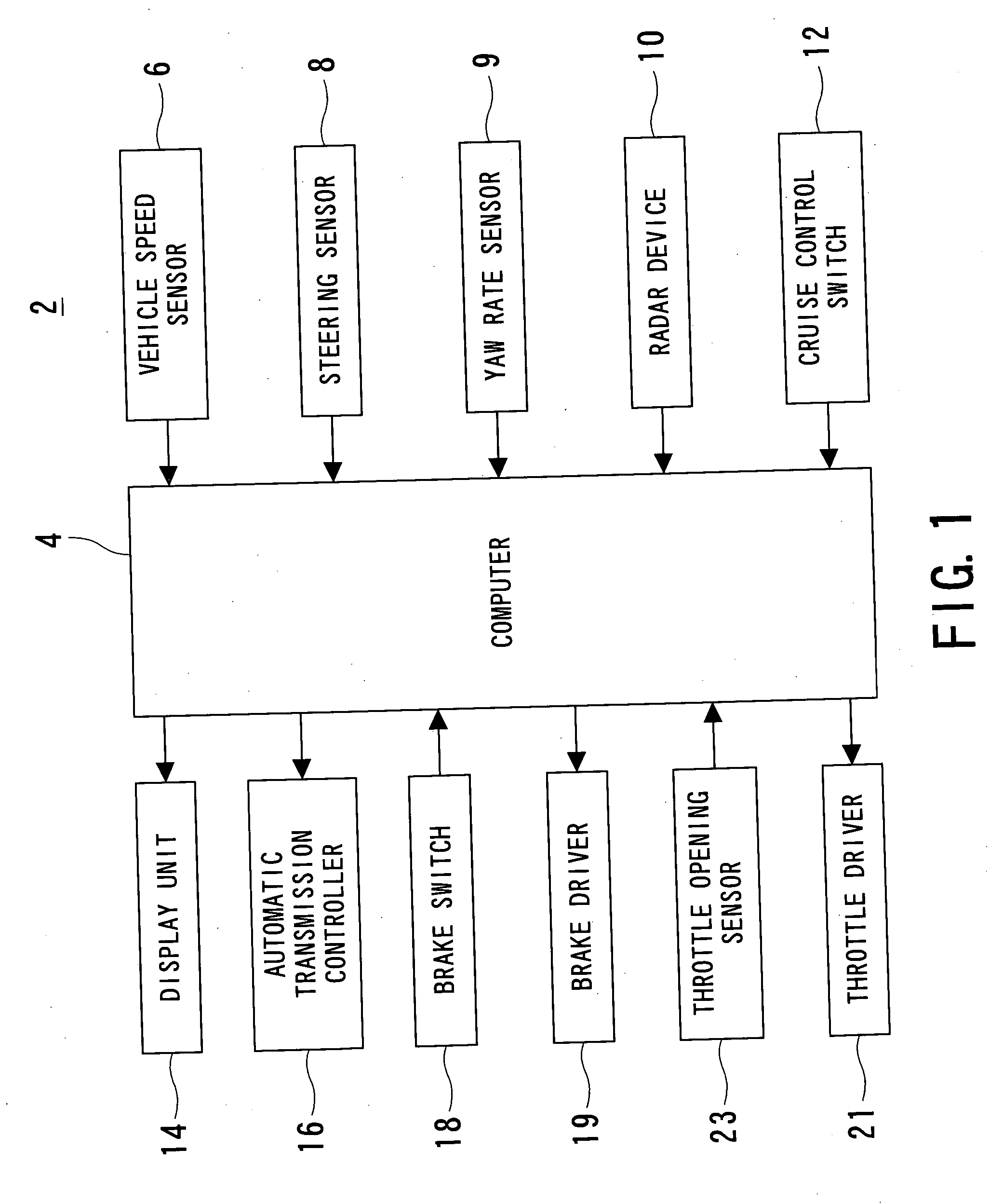
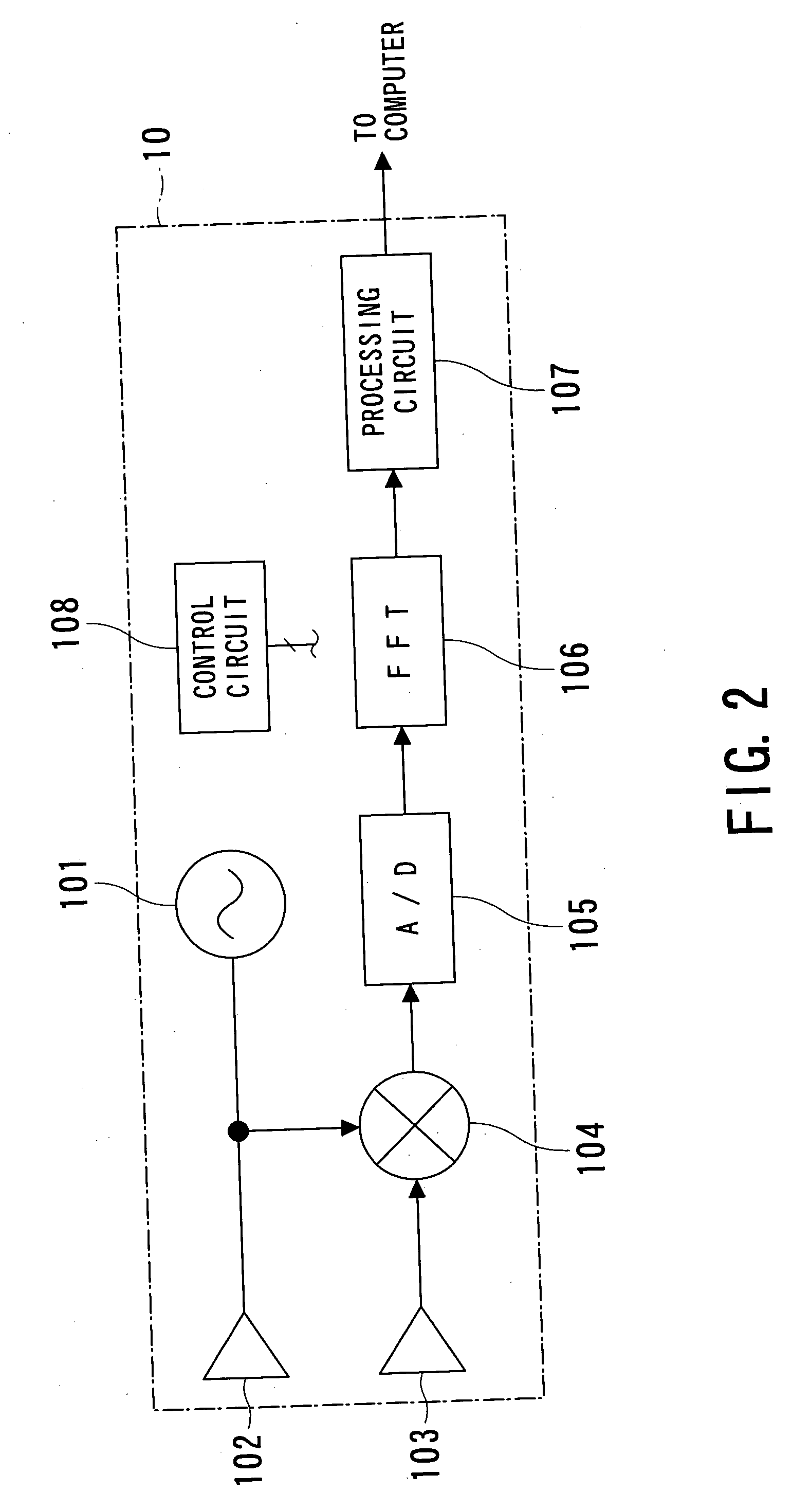
A third modification relates to variations of the radar device 10 that uses electromagnetic wave such as millimeter wave. The radar device 10 may be replaced by any other means such as laser light or ultrasound wave.


PUM


Abstract

An on-vehicle apparatus for recognizing objects is provided. The apparatus comprises a transmission/reception unit, detection unit, estimation unit, and specification unit. The transmission/reception unit transmits a medium wave toward a desired directional range from the vehicle and receives reflected waves of the medium wave and the detection unit detects objects existing in the desired directional range on the basis of the reflected wave. The estimation unit estimates a possibility that each detected object has been detected based on a reflected wave from a first part (e.g., cabin) of a further vehicle other than a second part (e.g., rear part) of the further vehicle, the first part being other than the second part that is the closest in distance to the apparatus-mounted vehicle. The specification unit specifies the second part as an object to finally be recognized of the apparatus-mounted vehicle depending on an estimated result by the estimation unit.

Description

BACKGROUND OF THE INVENTION 1. Technical Field The present invention relates to a method and apparatus for recognizing a vehicle preceding a vehicle on which the apparatus is mounted, and in particular, to the method and apparatus for recognizing a particular part, such as a rear part (i.e., object) of each preceding vehicle by making use of a radar device. 2. Related Art In recent years, much attention has been paid to research for creating a comfortable and safe traffic environment among researchers of automobiles and others. One type of apparatus dedicated to such research has been represented by Japanese Patent laid-open publication No. 2002-22827, in which a technique for recognizing objects is exemplified. In this publication, this technique is realized by a radar device, which transmits a radio wave toward certain directions to receive waves reflected from various objects existing ahead of the vehicle on which the radar device is mounted. This apparatus detects the inte...

Claims


Application Information

Patent Timeline
IPC IPC(8): G01S3/48G06T1/00G01S7/41G01S13/00G01S13/34G01S13/58G01S13/93G08G1/16
CPCG01S3/48G01S13/584G01S13/345G01S7/411
Inventor MATSUOKA, KEIJIKITAGAWA, HIDEKIANMA, HIROFUMIKAWAKUBO, ATSUSHIKAWASAKI, TOMOYA
Owner DENSO CORP
Why Eureka
Try Eureka