

Image displaying method and apparatus
a technology of image displaying and apparatus, applied in the field of mixed reality displaying technique, can solve problems such as the inability of the exhibitor to determine such situations
- Summary
- Abstract
- Description
- Claims
- Application Information
AI Technical Summary
Problems solved by technology
Method used
Image

Examples
first embodiment
[0027] The first embodiment describes a visual-field area exhibiting apparatus and method, utilized in a case where two workers each wearing a video see-through HMD perform cooperative work and share mixed reality space, and one of the workers exhibits the other worker a real object on which virtual data is superimposed.
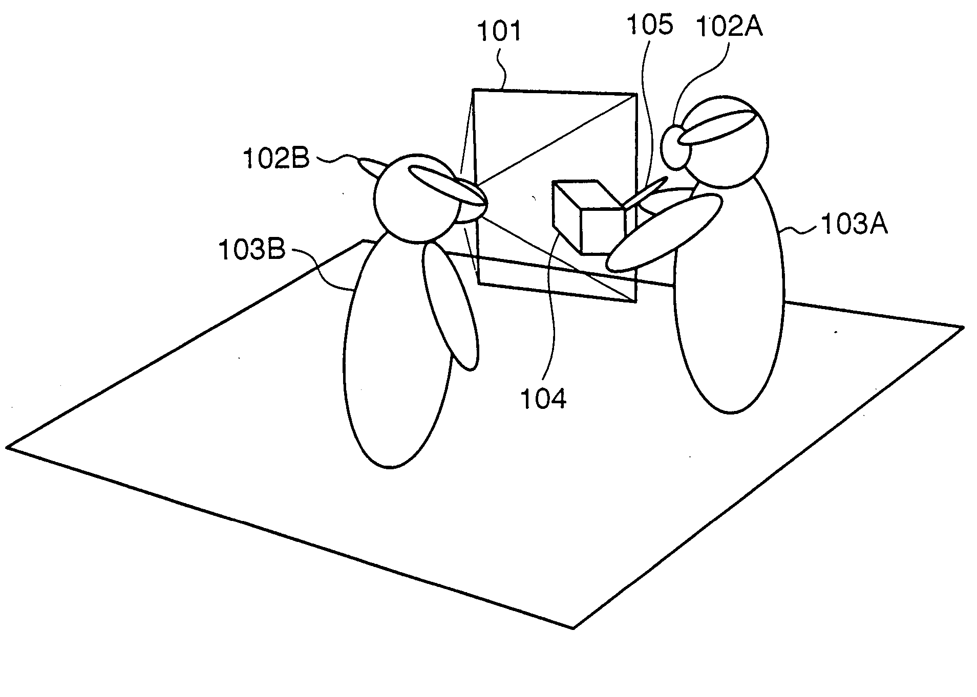
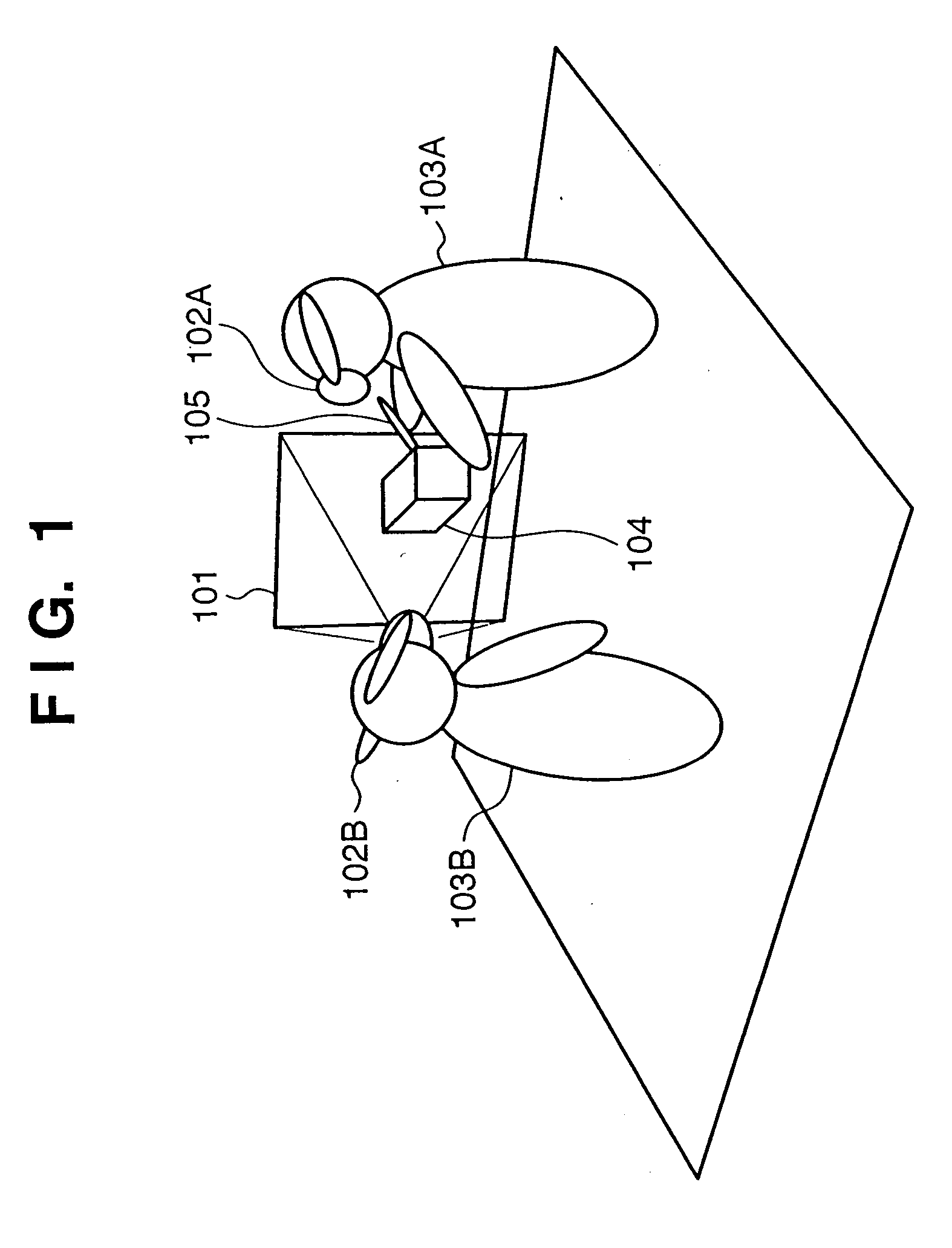
[0028]FIG. 1 is a schematic view for explaining an external appearance of the first embodiment in operation, to which the present invention is applied. Numeral 103A denotes a worker (hereinafter referred to as a exhibiter) who exhibits an object (hereinafter referred to as an exhibited object); and 103B, a worker (hereinafter referred to as an observer) who observes the exhibited object. The exhibiter 103A and the observer 103B share mixed reality space through respective video see-through HMDs 102A and 102B. The video see-through HMDs 102A and 102B in the first embodiment are a monocular video see-through HMD having one image sensing unit (not shown in FIG. 1). Acc...
second embodiment
[0054] In the above-described first embodiment, the exhibiter's HMD 102A and the observer's HMD 102B are a monocular HMD having a single image sensing unit. The second embodiment describes a visual-field area exhibiting apparatus in which at least the observer's HMD 102B is a binocular HMD (stereo HMD) having two image sensing units. Note that details of the stereo video see-through HMD 103B used in the second embodiment are described in the aforementioned Document 2.
[0055]FIG. 9 is a schematic view for explaining the shape of the visual-field object 101 according to the second embodiment. As described in the first embodiment, in a case of the monocular HMD, the view volume area is formed with one frustum of quadrangular pyramid. In a case of the stereo HMD, since an image is stereoscopically sensed, the view volume area is formed with two frusta of quadrangular pyramids 101L and 101R respectively having view points 301L and 301R as the vertices. The front clipping surfaces 302L an...
third embodiment
[0059] The first embodiment describes an example of a visual-field area exhibiting apparatus applying the present invention, where there is one observer and one exhibiter. However, the present invention does not limit the number of people of the observer and the exhibiter, and is applicable to a case where plural observers and plural exhibiters exist at the same time. The third embodiment describes a case where there is one exhibiter and two observers in the visual-field area exhibiting apparatus that is similar to the first embodiment.
[0060] Since there are two observers in the third embodiment, two visual-field areas are formed as shown in FIG. 10. To avoid a complicated diagram, a plan view is used in FIG. 10. The two observers are represented by numerals 103B and 103C. In the visual-field area exhibiting apparatus according to the third embodiment, an observer's HMD 102C and a MR image generating unit 404C are additionally included in the construction of the first embodiment sh...
PUM
| Property | Measurement | Unit |
|---|---|---|
| volume | aaaaa | aaaaa |
| visual-field area | aaaaa | aaaaa |
| area | aaaaa | aaaaa |
Abstract
Description
Claims
Application Information