
Method and apparatus for ink jet printing on rigid panels

Inactive Publication Date: 2005-02-03
L & P PROPERTY MANAGEMENT CO
View PDF76 Cites 17 Cited by
  • Summary
  • Abstract
  • Description
  • Claims
  • Application Information

AI Technical Summary

Benefits of technology

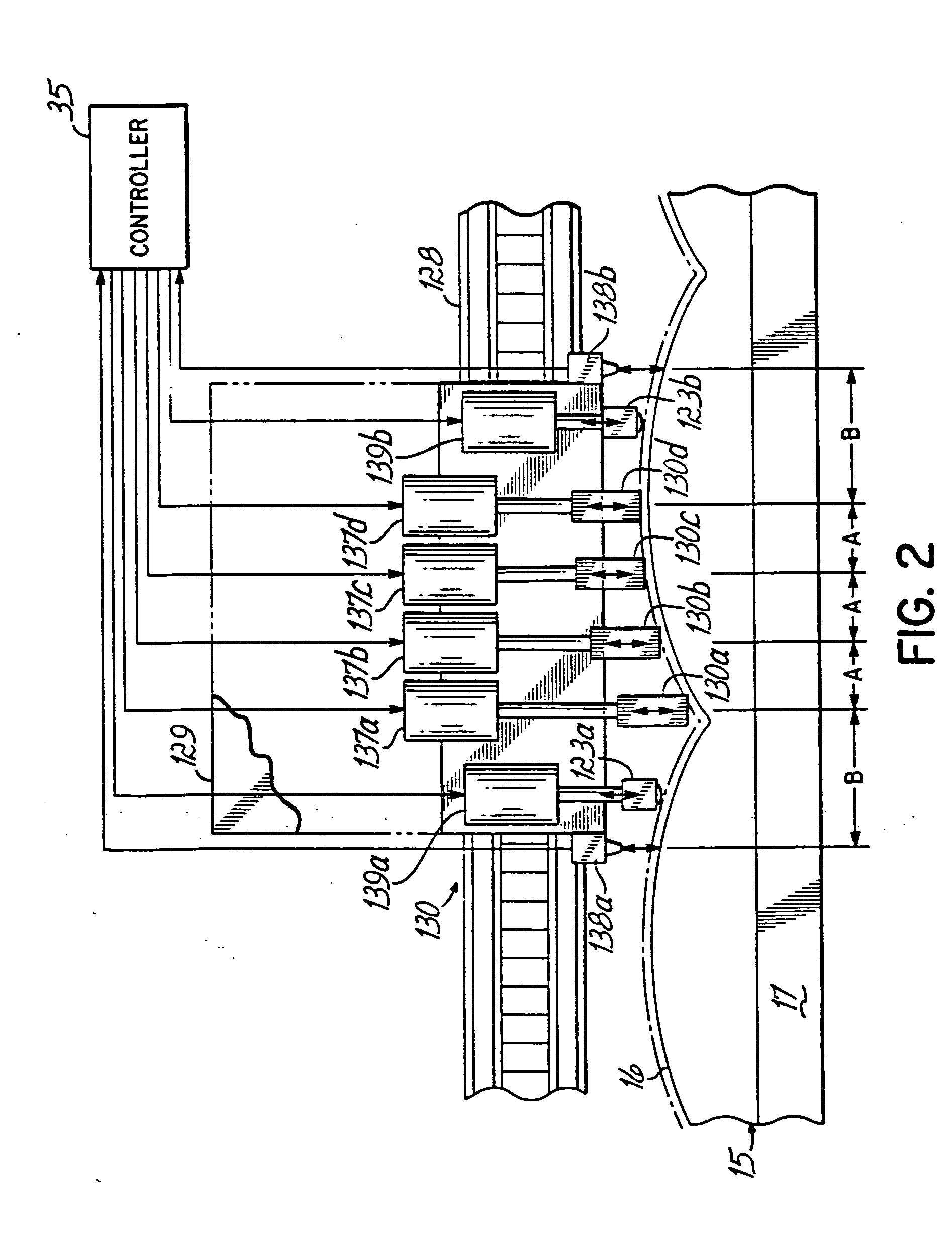
[0008] According to the principles of the present invention, printed images are applied to rigid substrates with printing elements that may be moveable relative to the plane of the substrate being printed. In certain embodiments, the invention provides a wide-substrate ink jet printing apparatus with printheads that move toward and away from the plane of a substrate to maintain a fixed distance between the nozzles of the printhead and the surface onto which the ink is being jetted. The variable distance over the plane of the substrate allows a controlled and uniform distance across which the ink is jetted.
[0011] According to the preferred embodiment of the invention, UV ink is printed onto material and the cure of the ink is initiated by exposure to UV light radiated from UV curing lights mounted on the printhead carriage, one on each side of the printhead set. The lights are alternatively energized, depending on the direction of motion of the carriage across the substrate, so as to expose the printed surface immediately behind the heads. By so mounting the UV curing lights on the printhead carriage, the jetted ink can “spot cure” the ink, or to cure the ink immediately upon its contacting the substrate. Such spot curing “freezes the dots” in position and prevents their spreading on or wicking into or otherwise moving on the substrate. With certain substrates, conventional or broad spectrum UV curing lights include radiation that can heat the substrate. Such radiation includes infra-red radiation and radiation of such other wavelengths that tend to heat a particular substrate.
[0014] The present invention provides the use of cold UV sources for spot curing of UV curable ink on heat sensitive rigid substrates. Heat caused deformation of the substrate in the region of the printing operation is prevented with the use of a cold UV source, Such a cold UV source can, for example, be a limited bandwidth UV source, to limit energy of wavelengths that are not effective to cure the ink from otherwise striking and heating the substrate. This can be carried out with selective bandwidth sources or with the use of filters to remove energy of undesired wavelengths. Alternatively, heat removal can be employed to remove the heat that is produced by the curing radiation. The cold UV source is useful for printing onto substrates that can deform, even temporarily, when heated, and is particularly useful where spot curing of the ink can otherwise result in the deformation of the material on which printing is still to take place.
[0015] Deformation at the printing site, even if temporary such that the material returns to its undeformed state when it cools, adversely affects the print quality because spot curing deforms the substrate as the ink jets are making single or multiple passes over the print area. This is particularly the case when printing onto foamboards that make up the largest application of printing onto rigid substrates. Such deformation of the board from heat during printing would force adjustment of the head height above the deformation zone. Higher head height usually results in poorer print quality. With a cold-UV spot-cure ink-jet system, the head-to-substrate distance can be minimized to maximize print quality.

Problems solved by technology

If the distance from the nozzles to the surface being printed is too great, deviations from ideal parallel paths of the drops from different nozzles become magnified.
Additionally, droplet shape changes the farther the drop moves from the nozzle, which changes the effects of the drop on the substrate.
Accordingly, variations in the distance from the printhead to the substrate can cause irregular effects on the printed image.
In addition to problems in jetting ink onto contoured surfaces, the curing of UV inks requires delivery of sufficient curing energy to the ink, which is often difficult to achieve where the surface is contoured.
Further, some substrates deform, even temporarily, when heated.
Nonetheless, even temporary deformation can adversely affect the print quality if it exists when ink is being jetted onto the substrate.
For these reasons, ink jet printing has not been successful on contoured materials and other three-dimensional substrates, particularly when printing with UV curable inks.

Method used


Image

  • Method and apparatus for ink jet printing on rigid panels
  • Method and apparatus for ink jet printing on rigid panels
  • Method and apparatus for ink jet printing on rigid panels

Examples


Embodiment Construction

[0023] Ink jet printing onto large rigid substrates is described in the commonly assigned and copending U.S. patent applications Ser. Nos. 09 / 650,596, filed Aug. 30, 2000, and 09 / 822,795, filed Mar. 30, 2001, hereby expressly incorporated by reference herein. Ink jet printing onto large substrates, particularly textiles, is described in the commonly assigned and copending U.S. patent applications Ser. No. 09 / 390,571, filed Sep. 3, 1999, Ser. No. 09 / 823,268, filed Mar. 30, 2001 and Ser. No. 09 / 824,517, filed Apr. 2, 2001, and International Application Serial No. PCT / US00 / 24226, filed Sep. 1, 2000, each hereby expressly incorporated by reference herein.

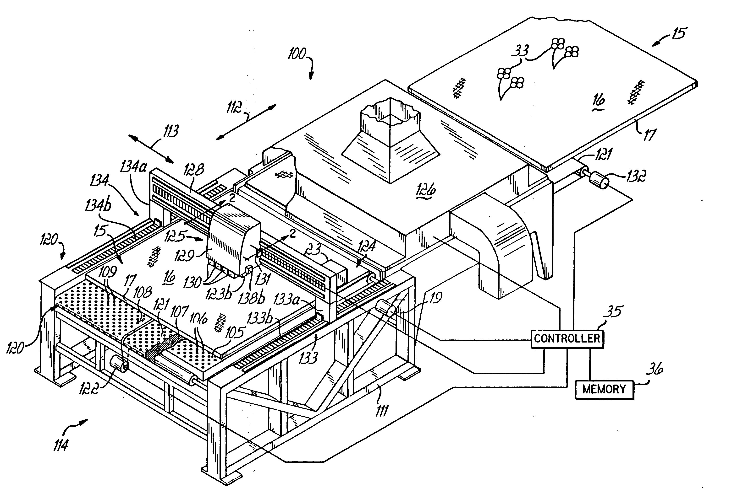
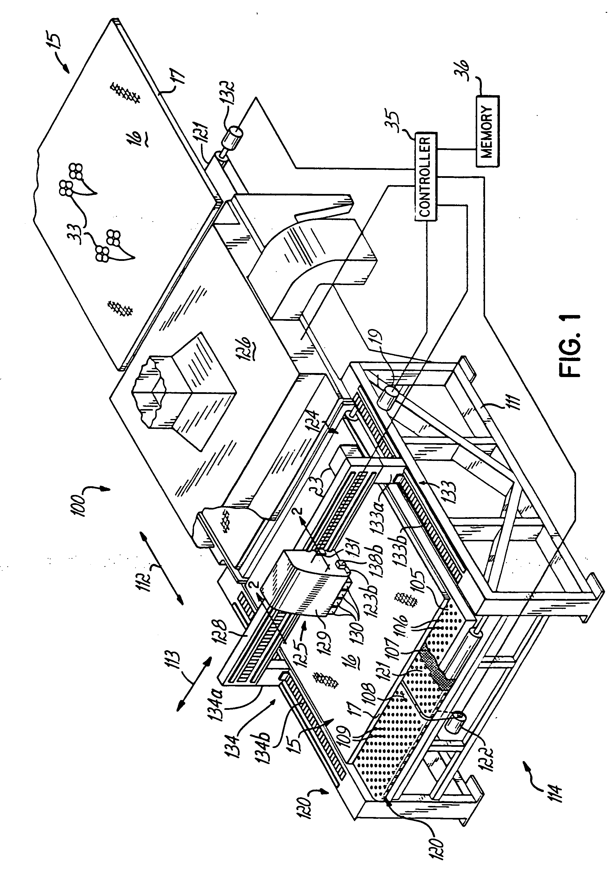
[0024]FIG. 1 illustrates an ink jet printing machine 100 for printing onto wide rigid substrates. The machine 100 includes a stationary frame 111 with a longitudinal extent represented by an arrow 112 and a transverse extent represented by an arrow 113. The machine 100 has a front end 114 into which the rigid panel 15 may be loaded ont...


PUM

PropertyMeasurementUnit
Lengthaaaaaaaaaa
Distanceaaaaaaaaaa
Wavelengthaaaaaaaaaa

Abstract

Ink jet printing is provided onto rigid panels such as foamboard and contoured material using ultraviolet (UV) light curable ink, which is first at least partially cured with UV light and then may be subjected to heating. Printhead-to-panel spacing is controllable to maintain a predetermined constant distance from the printing element to the surface of the panel where the ink is to be applied. Each of a plurality of printheads may be independently moveable to control the spacing of the printheads from the substrate surface. Sensors on the printhead carriage measure the shape, or vertical position of, the printhead's distance from the printhead carriage to the surface of the substrate being printed. The position or focal length of the UV light curing head may be varied to maintain focus of the UV light on the ink on a contoured surface of the substrate. UV curing heads may be located on the printhead carriage, one on each side of the printheads, and activated alternately as the carriage reciprocates, to spot cure and freeze the dots of ink immediately after being deposited on the substrate. Cold UV sources may be used to prevent heat deformation of flat or contoured substrates during printing, thereby making spot curing on heat-sensitive substrates such as foamboard possible.

Description

[0001] This application is a continuation of application Ser. No. 09 / 989,006, filed on Nov. 21, 2001, which is a continuation-in-part of PCT Application No. PCT / US01 / 27023 filed Aug. 30, 2001, the disclosure of which is hereby expressly incorporated by reference herein.FIELD OF THE INVENTION [0002] The present invention relates to printing onto rigid substrates, and to the printing onto textured, contoured or other three-dimensional substrates. The invention is particularly related to the printing onto such substrates as those having textile fabric surfaces or molded objects, rigid panels such as office partitions, automobile interior panels and other contoured objects, and to such printing using ink jet printing techniques. BACKGROUND OF THE INVENTION [0003] Applying ink to a substrate by ink jet printing requires a proper spacing between the ink jet nozzles and the surface of the substrate to which the printing is applied. Normally, this spacing must be set to within one or two mi...

Claims


Application Information

Patent Timeline
IPC IPC(8): B41J3/407B41J11/00B41J25/308D06P5/20D06P5/30
CPCB41J3/28B41J3/4073B41J3/4078B41J11/0015B41J11/002B41J11/0085B41M7/009B41J25/3086B41M7/0072D06P5/2005D06P5/30B41M7/0081B41J25/308B41J11/00214B41J11/00218B41J11/0022B41J2/01
Inventor CODOS, RICHARD N.
Owner L & P PROPERTY MANAGEMENT CO
Learn More