Graphical user interface for system status alert on videoconference terminal

a videoconferencing terminal and status alert technology, applied in the field of graphical user interfaces, can solve problems such as the relatively complex nature of videoconferencing systems

Inactive Publication Date: 2005-02-03
HEWLETT PACKARD DEV CO LP
View PDF14 Cites 145 Cited by
  • Summary
  • Abstract
  • Description
  • Claims
  • Application Information

AI Technical Summary

Problems solved by technology

Videoconferencing sys...

Method used


Image

  • Graphical user interface for system status alert on videoconference terminal
  • Graphical user interface for system status alert on videoconference terminal
  • Graphical user interface for system status alert on videoconference terminal

Examples


Embodiment Construction

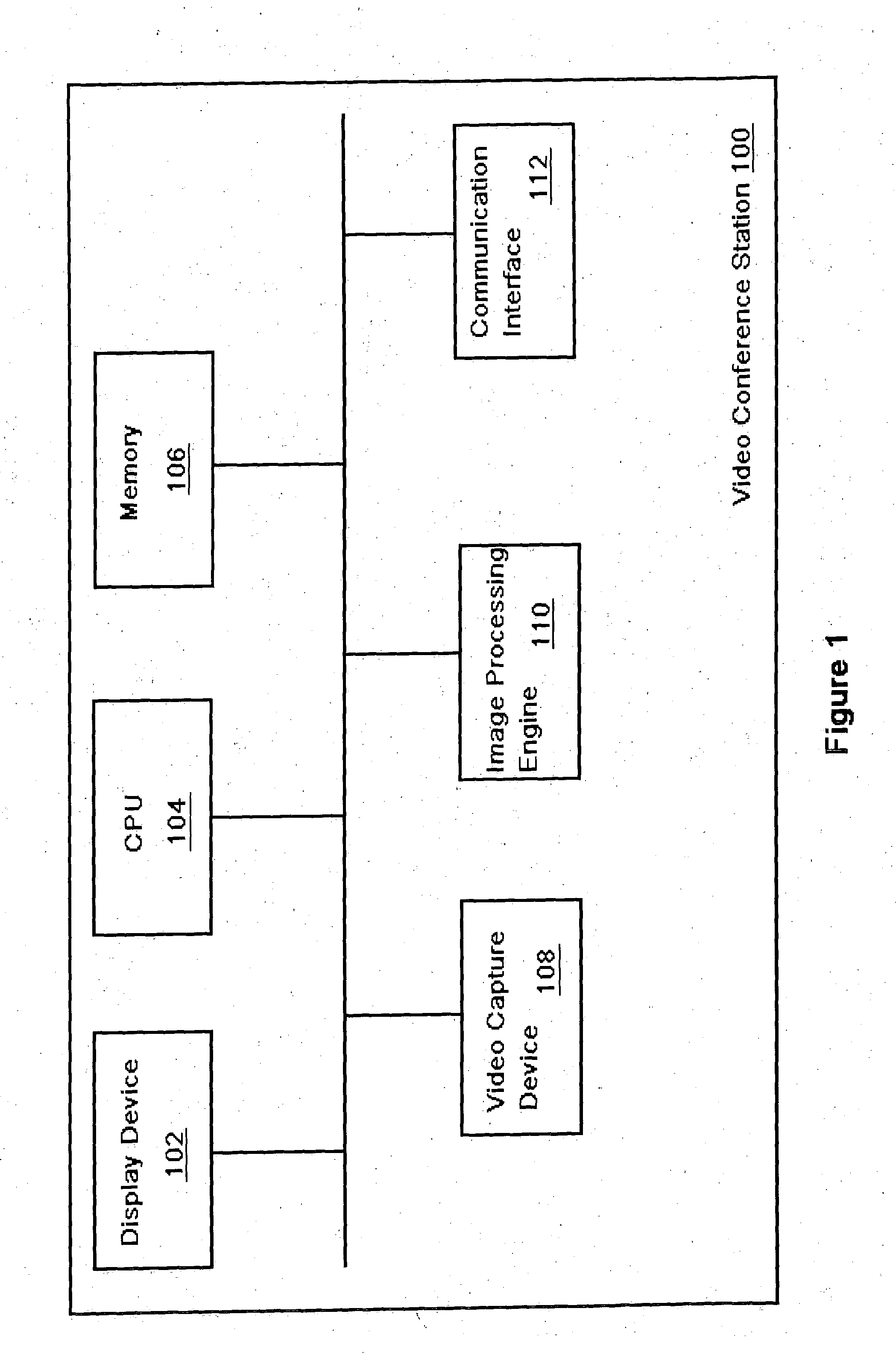
[0016]FIG. 1 is a block diagram of an exemplary video conference station 100. For simplicity, the video conference station 100 will be described as the local video conference station, although the remote video conference station may contain a similar configuration. In one embodiment, the video conference station 100 includes a display device 102, a CPU 104, a memory 106, at least one video capture device 108, an image processing engine 110, and a communication interface 112. Alternatively, other devices may be provided in the video conference station 100, or not all above-named devices provided. The at least one video capture device 108 may be implemented as a charge couple device (CCD) camera, a complementary metal oxide semiconductor (CMOS) camera, or any other type of image capture device. The at least one video capture device 108 captures images of a user, conference room, or other scenes, and sends the images to the image processing engine 110. Typically, the image processing e...


PUM


Abstract

The Graphical User Interface (GUI) of a videoconference terminal is provided with user-selectable icons which are associated by the user with various video signals. Textual labels for the various video signals may also be provided. This information may be exchanged with the “far end” participant in the video conference. During the videoconference participants may then simply select an icon to dynamically switch video feeds without having to remember by number the particular camera or other video signal associated with a desired video feed.

Description

BACKGROUND [0001] 1. Field of the Invention [0002] This invention relates to videoconferencing systems. More particularly it relates to Graphical User Interfaces used to control the operation of a video conference terminal. [0003] 2. Description of the Related Art [0004] Videoconferencing systems are relatively complex. They typically involve a plurality of video signals, audio signals, processors, apparatus and / or software for data compression and decompression, directional microphones, speakers, video display units, feedback-prevention circuits, cameras and connections to telecommunications networks with associated interface devices. [0005] Systems and methods which alleviate the complexity of videoconferencing systems and simplify the user interface help to gain mass-market acceptance of videoconferencing as an alternative to in-person meetings which often involve travel to a remote location. As has been demonstrated in the personal computer industry, one particularly successful ...

Claims


Application Information

Patent Timeline
IPC IPC(8): H04N5/445H04N7/14H04N7/15
CPCH04N7/147H04N7/15H04N21/4223H04N21/4316H04N21/8146H04N21/47H04N21/4788H04N21/4823H04N21/485H04N21/4622
Inventor CASTLES, RANDYSEXTON, MARTINNIMRI, ALAIN
Owner HEWLETT PACKARD DEV CO LP
Why Eureka
Try Eureka