Broadband single conversion tuner integrated circuits

a technology of integrated circuits and transceivers, applied in the field of radio frequency (rf) receivers, can solve problems such as harmonics, spurious signals, and other undesired signals

Active Publication Date: 2005-02-03
MAXIM INTEGRATED PROD INC
View PDF7 Cites 46 Cited by
  • Summary
  • Abstract
  • Description
  • Claims
  • Application Information

AI Technical Summary

Problems solved by technology

These unwanted signals include image, harmonics, spurious, and other undesired signals.

Method used


Image

  • Broadband single conversion tuner integrated circuits
  • Broadband single conversion tuner integrated circuits
  • Broadband single conversion tuner integrated circuits

Examples


Embodiment Construction

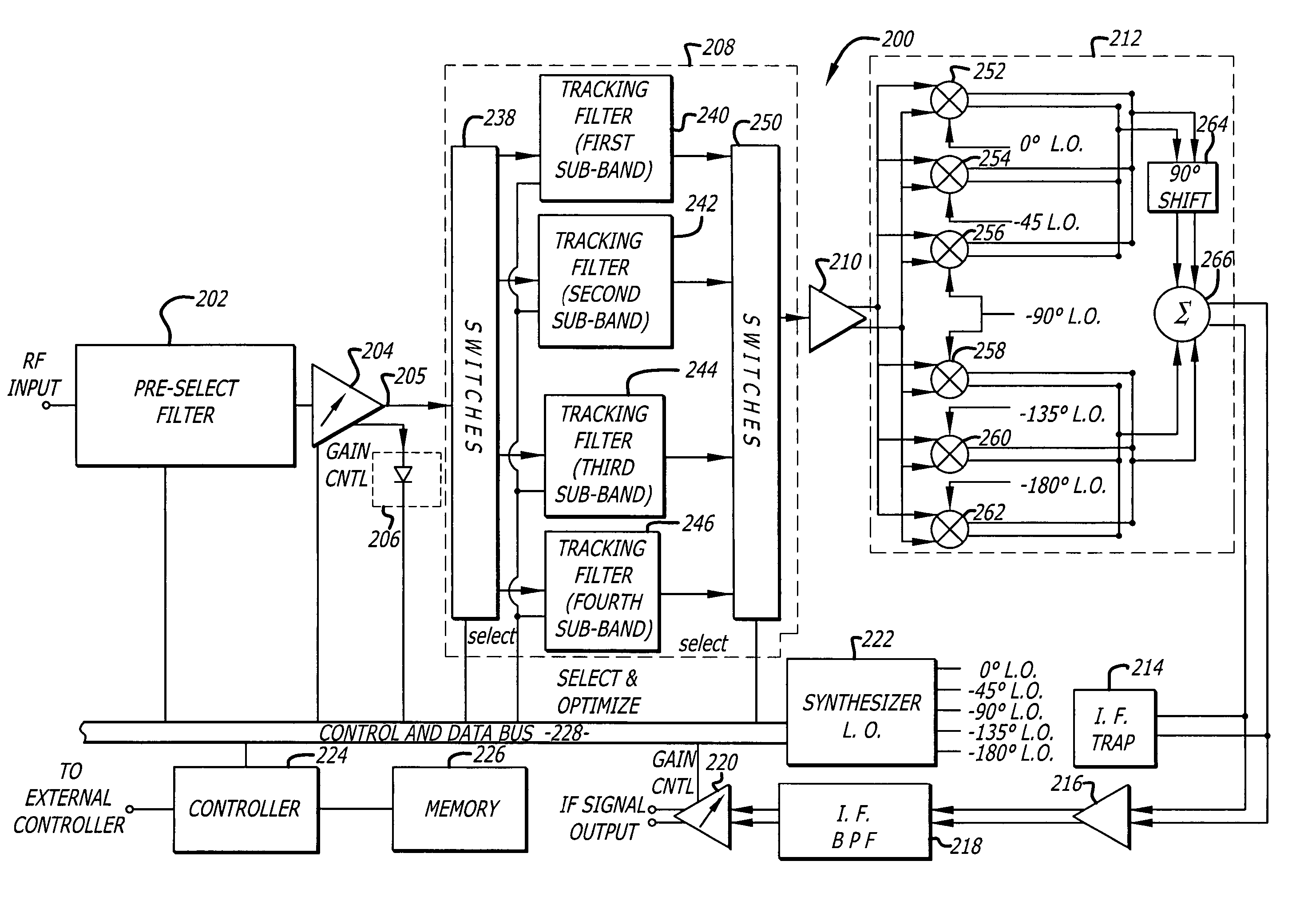
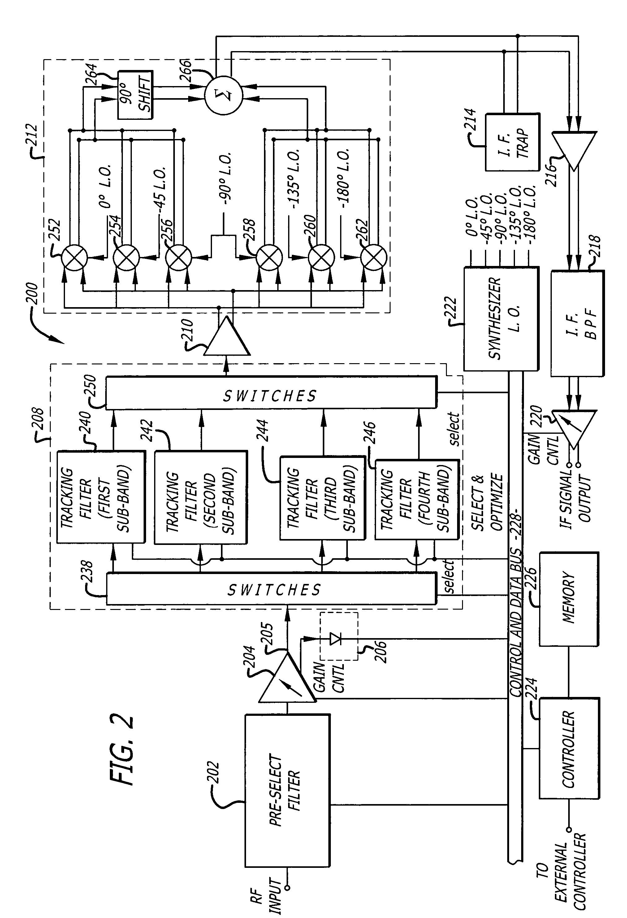
[0017] I. The Tunable Receiver Design

[0018]FIG. 2 is a block diagram of an exemplary tunable receiver 200 in accordance with an embodiment of the invention. The tunable receiver 200 comprises a preselect filter 202, a first low noise amplifier (LNA) 204 having a controllable gain and an associated output power monitor device 206, a bank of selectable and digitally-tunable tracking filters 208, a second LNA 210, a harmonic and image reject down converting stage 212, an intermediate frequency (IF) trap 214, a first IF amplifier 216, an IF band pass filter (BPF) 218, and a second IF amplifier 220 having a controllable gain. In addition, the tunable receiver 220 comprises a synthesizer local oscillator (L.O.), a controller 224, a memory 226, and a control and data bus 228.

[0019] More specifically, details of an embodiment of the preselect filter 202 is shown in FIG. 11. The circuit includes two on-chip spiral inductors, L0 and L1, two fixed capacitors, C0 and C1, two MOSFET switches, ...


PUM


Abstract

A tunable receiver is disclosed including a plurality of select filters to perform an initial band selection, a variable-gain low noise amplifier (LNA) whose gain is controlled to prevent its output power level to exceed a pre-determined power threshold, a plurality of digitally-tunable tracking filters to pass signals within a selected channel and to reject signals in a corresponding image band, a second LNA to further amplify the received RF signal and to generate differential signal outputs, a down converting stage which converts the received RF signal to an IF signal while rejecting signals in the image band, an IF trap to further reject undesired signals present at the output of the down converting stage, an IF amplifier to amplify the IF signal to compensate for losses, an IF filter to provide channel select and reject undesirable signals, and a variable-gain IF amplifier to amplify the IF signal and maintain its power level within specification.

Description

FIELD OF THE INVENTION [0001] This invention relates generally to radio frequency (RF) receivers, and in particular, to integrated, tunable television receivers comprising a single down converting stage and several stages for substantially rejecting the image, harmonics, and other unwanted signals. BACKGROUND OF THE INVENTION [0002] Tunable receivers used in cable television set-top boxes and in other applications receive broadband signals having many channels. It is a function of such a tunable receiver to produce the signals in a desired channel and reject the signals in the remaining channels. In rejecting the signals in the undesired channels, the tunable receiver should substantially remove all signals associated with the undesired channels so that the receiver outputs substantially the signals in the desired channel. These unwanted signals include image, harmonics, spurious, and other undesired signals. [0003] Both single conversion and double conversion receivers are known in...

Claims


Application Information

Patent Timeline
Patent Type & Authority Applications(United States)
IPC IPC(8): H03D3/00H03J5/24H04N5/50
CPCH03D3/007H03J5/244H04N21/426H04N5/50H03J2200/10
Inventor WAIGHT, MATTHEW GLENNBIRKELAND, JOEL DAVIDPRESTRELSKI, FRANK PAUL
Owner MAXIM INTEGRATED PROD INC
Why Eureka
Try Eureka