Servo control method and servo control circuit, and optical disk device having the same servo control circuit

Inactive Publication Date: 2005-02-03
SONY CORP
View PDF0 Cites 9 Cited by
  • Summary
  • Abstract
  • Description
  • Claims
  • Application Information

AI Technical Summary

Benefits of technology

[0061] Furthermore, in the defect detection signal generation circuit which generates the defect detection signal, the changeover timing delay circuit is provided which delays the timing to change the hold signal to the servo control signal based on the defect detection signal, so that when the hold signal is changed to the servo control signal, the signal which has the fluctuation component can be prevented from being inputted into the servo control signal generation circuit, thus promptly outputting the normal servo control signal and stably performing the servo control immediately after returning from the hold state.
[0062] Still further, in the optical disk device for generating the servo control signal, for generating the hold signal and the defect detection signal from the output signal of the pickup unit, and having the servo control circuit which changes over to either the servo control signal or the hold signal based on the defect detection signal so as to perform the servo control of the pickup unit, the servo control signal generation circuit which generates the servo control signal is connected to the status variable memory circuit which stores the status variables of the servo control signal generation circuit; when changing the servo control signal to the hold signal, the servo control signal generation circuit is arranged to use the predetermined status variables out of the status variables stored in the status variable memory circuit; when changing the servo control of the pickup unit by means of the hold signal to the servo control by means of the servo control signal, the servo control signal generation circuit resumes the generation of the servo control signal based on the proper status variables, thus promptly outputting the normal servo control signal and stably performing the servo control immediately after returning from the hold state. Therefore, the operational stability of the optical disk device can be improved.
[0063] Further, in the defect detection signal generation circuit which generates the defect detection signal by means of the input signal read from the recording media, the first and second signal detection circuits are provided where the tracking ability with respect to the above-mentioned input signal at the time of the rise and fall of the above-mentioned input signal differs, and the first and second detection signals detected in the first and the second signal detection circuits are compared to generate the defect detection signal, so that even if a bright defect occurs at the time of playba

Problems solved by technology

Furthermore, the defect detection signal generation circuit which generates the defect detection signal is characterized by having a changeo

Method used


Image

  • Servo control method and servo control circuit, and optical disk device having the same servo control circuit
  • Servo control method and servo control circuit, and optical disk device having the same servo control circuit
  • Servo control method and servo control circuit, and optical disk device having the same servo control circuit

Examples


Example

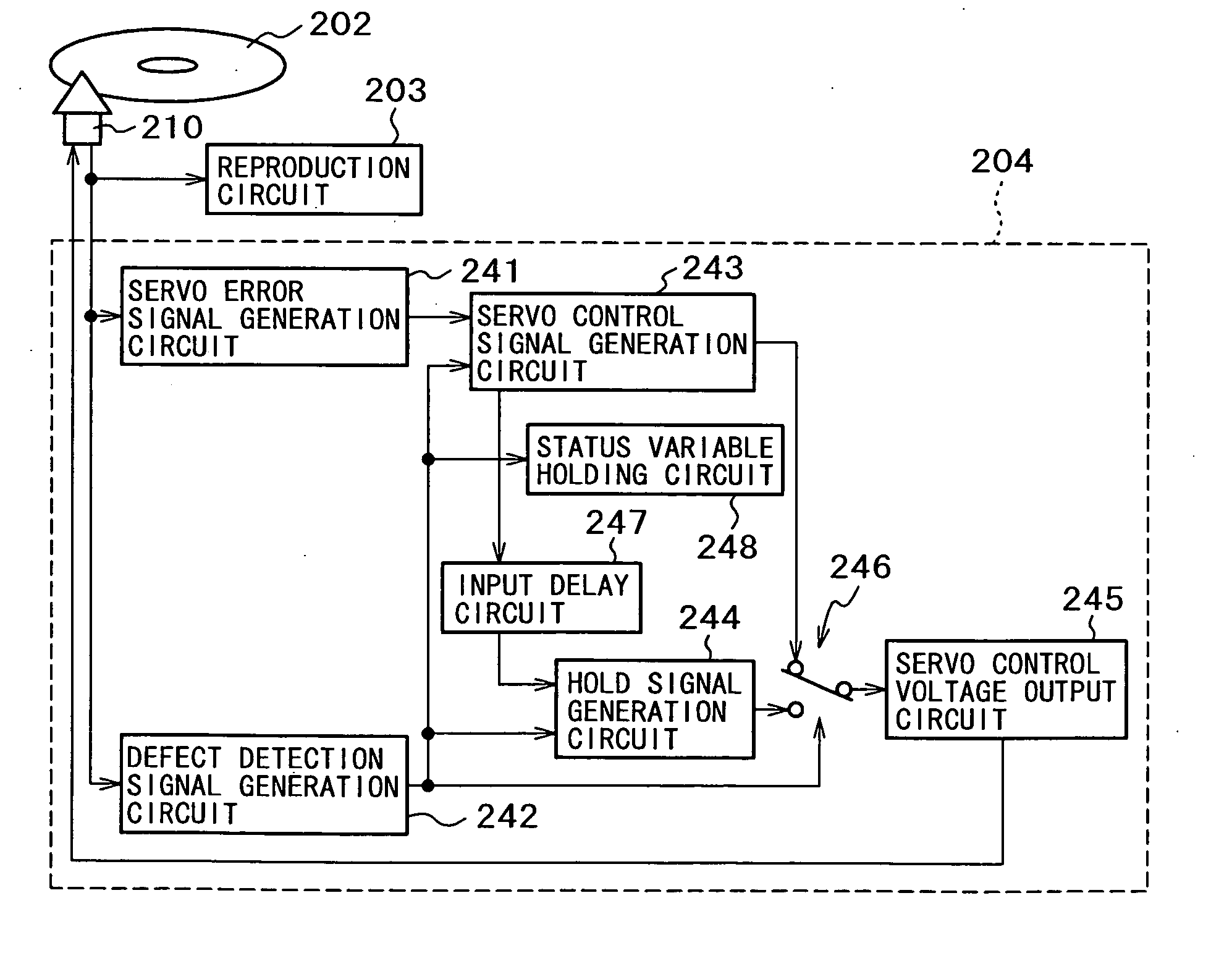
[0092] An optical disk record / playback apparatus in accordance with the present invention has a reproduction circuit therein for reproducing data recorded on an optical disk as a recording media.

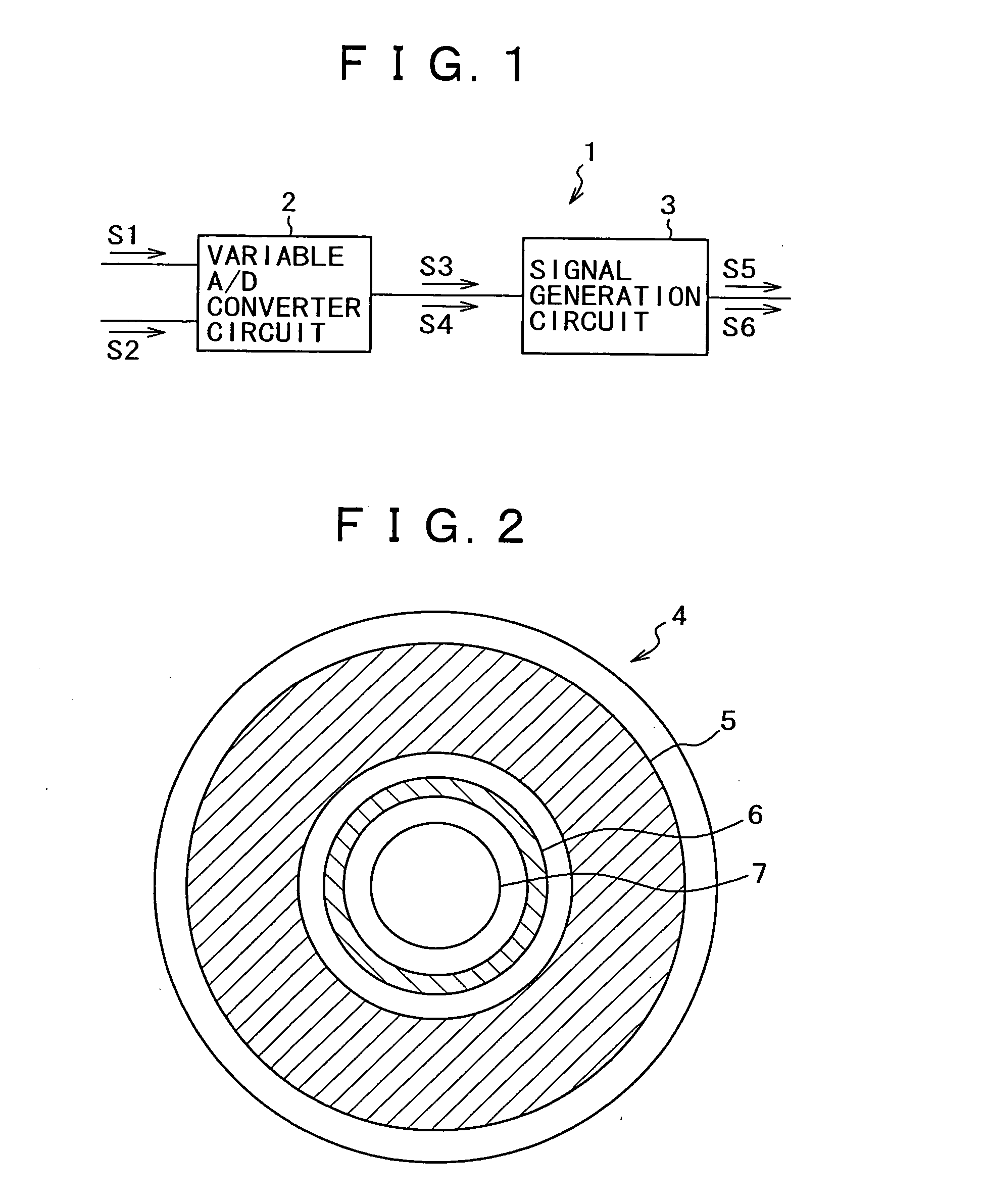
[0093] This reproduction circuit has a single variable A / D converter circuit and a single signal generation circuit.

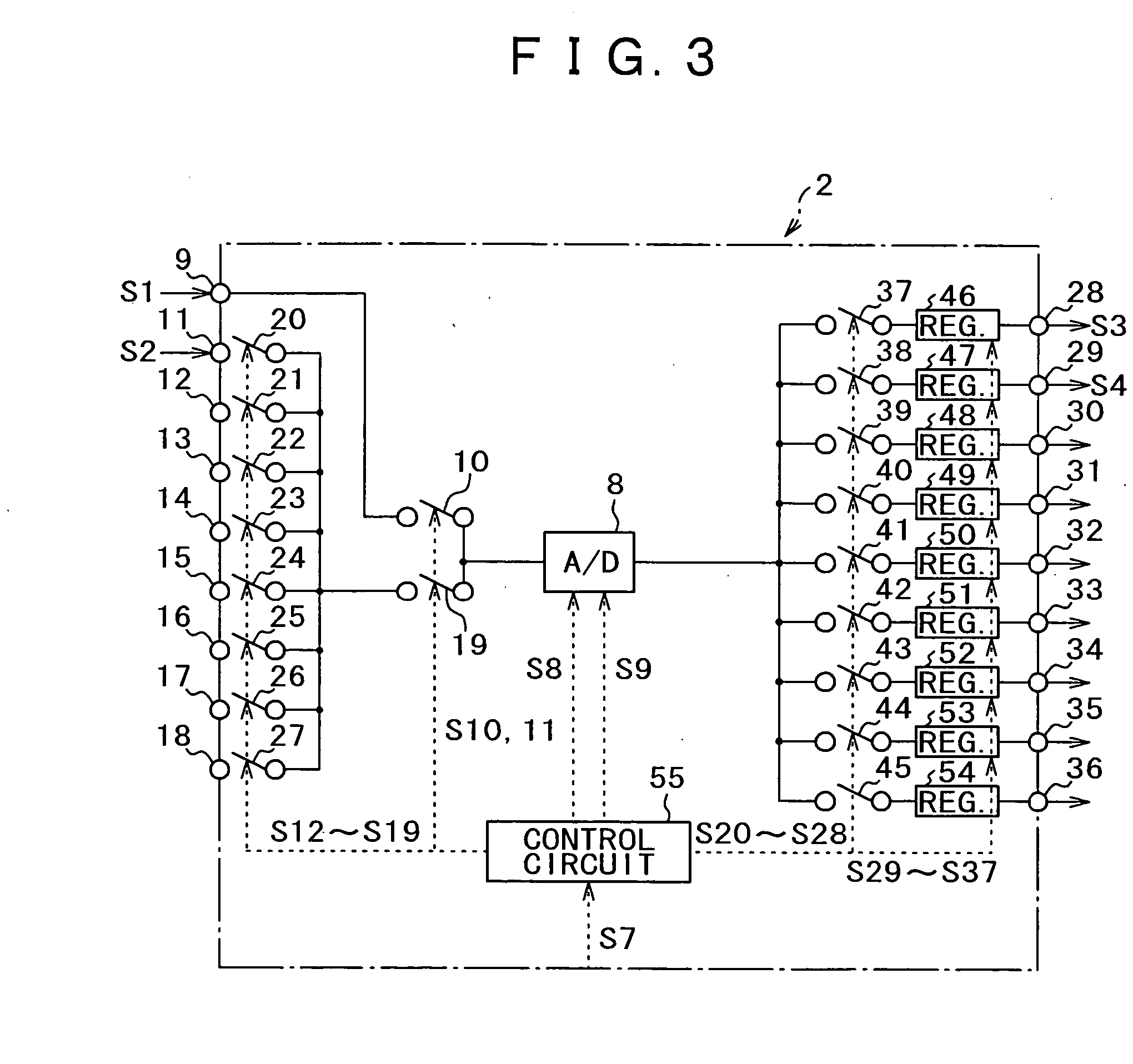
[0094] The variable A / D converter circuit herein is a circuit for converting a first and a second analog signals read from a first and a second record areas which differ from each other and are on a recording media, into a first and a second digital signals respectively with different sampling rates.

[0095] This variable A / D converter circuit connects the first and the second analog signals to an A / D converter circuit through the first and second switches, and is arranged to control these first and second switches by a control circuit which intermittently switches them with the different sampling rates.

[0096] Further, the signal generation circuit is a circuit for generating...


PUM


Abstract

A servo error signal and a defect detection signal are generated from an output signal of the pickup unit, and a servo control signal and a hold signal are generated from the servo error signal. When changing to either a servo control signal or a hold signal based on the defect detection signal generated in a defect detection signal generation circuit which has a peak hold circuit having different tracking ability, so as to perform servo control of the pickup unit, a servo error signal predetermined time before a timing to change from the servo control signal to the hold signal is used as the servo error signal used for generation of the hold signal.

Description

BACKGROUND OF THE INVENTION [0001] 1. Field of the Invention [0002] The present invention relates to a servo control method and a servo control circuit, and an optical disk device having the servo control circuit. [0003] 2. Description of the Related Art [0004] In recent years, an optical disk has been used widely as a mass recording media which can record a lot of data. [0005] A data recorded on this optical disk is reproduced in such a way that an input signal read from the optical disk by means of an optical disk playback apparatus is processed in a signal processing circuit. [0006] In this case, the optical disk playback apparatus generates various control signals such as a tracking control signal and a focus control signal from the input signal read from the optical disk, and further generates a defect detection signal which indicates defects on the optical disk so as to control the internal circuits of the optical disk playback apparatus according to these control signals and ...

Claims


Application Information

Patent Timeline
IPC IPC(8): G11B7/00G11B7/09G11B20/18G11B21/03
CPCG11B7/0948G11B20/1816G11B20/18G11B7/09
Inventor INOUE, YUKIOYAMAGUCHI, KAZUYUKIKUSANO, TAIZOUHAYASHIDA, KAZUHISAUDO, YUICHIFUJIMOTO, YUKOKURIYAMA, HIROMIOOISHI, TAKASHIKANEO, YASUHIROANDO, RYO
Owner SONY CORP
Why Eureka
Try Eureka