
Dispersion-compensated optical wavelength router and cascaded architectures

Inactive Publication Date: 2005-02-03
EC OPTICS TECH
View PDF14 Cites 6 Cited by
  • Summary
  • Abstract
  • Description
  • Claims
  • Application Information

AI Technical Summary

Benefits of technology

The following technical advantages may be achieved by some, none, or all of the embodiments of the present invention. The optical wavelength router performs a multiplexing and/or a demultiplexing function to generate output waveforms that have

Problems solved by technology

As transmission systems evolve to longer distances, smaller channel spacings, and

Method used


Image

  • Dispersion-compensated optical wavelength router and cascaded architectures
  • Dispersion-compensated optical wavelength router and cascaded architectures
  • Dispersion-compensated optical wavelength router and cascaded architectures

Examples


first modified embodiment

FIGS. 16A and 16B illustrate the dispersion profiles of modified embodiments of wavelength router 10. In router 10, referred to hereinafter as router 1600, the optical thickness d2 of resonator 30b is selected so that resonator 30b has a free spectral range (FSR) of approximately 50 GHz and the resonance frequencies are at fc−6.25 GHz. Here fc denotes the center frequencies of the WDM channels of input signal 12 that are spaced, for example, 50 GHz apart. The FSR of resonator 30b here is defined as the period of the resonator's complex reflectivity.

The above conditions are achieved by following the equation:

d2=(m / 2)*λc+({fraction (1 / 16)}).*λc

and picking the integer m such that the equation:

d2=c / (2*FSR)

is satisfied to best approximation. Here, λc is the center wavelength of any one of the input channels within the FSR of the particular resonator 30; and c is the speed of light in a vacuum. In a particular embodiment, λ.c is the center wavelength of the center input channel wit...

second modified embodiment

the router 10, referred to hereinafter as router 1610, can be constructed by exchanging the optical thicknesses of resonators 30a and 30b. For example, router 1600 yielding the performance characteristic illustrated in FIG. 16A can have resonator 30a with optical thickness, d1=2.997824, and resonator 30b with optical thickness, d2=2.998017, as determined above. Router 1610 yielding the dispersion profile illustrated in FIG. 16B can have resonator 30a with optical thickness, d1=2.998017, and resonator 30b with optical thickness, d2=2.997824. Note that each period of the chromatic dispersion profile has a negative slope for a first range of frequencies and a positive slope for a second range of frequencies. Therefore, by exchanging the optical thicknesses of resonators 30a and 30b from router 1600 to router 1610, the chromatic dispersion profile is inverted about the center frequency along the x-axis and inverted about the zero dispersion measurement about the y-axis.

By following the...


PUM


Abstract

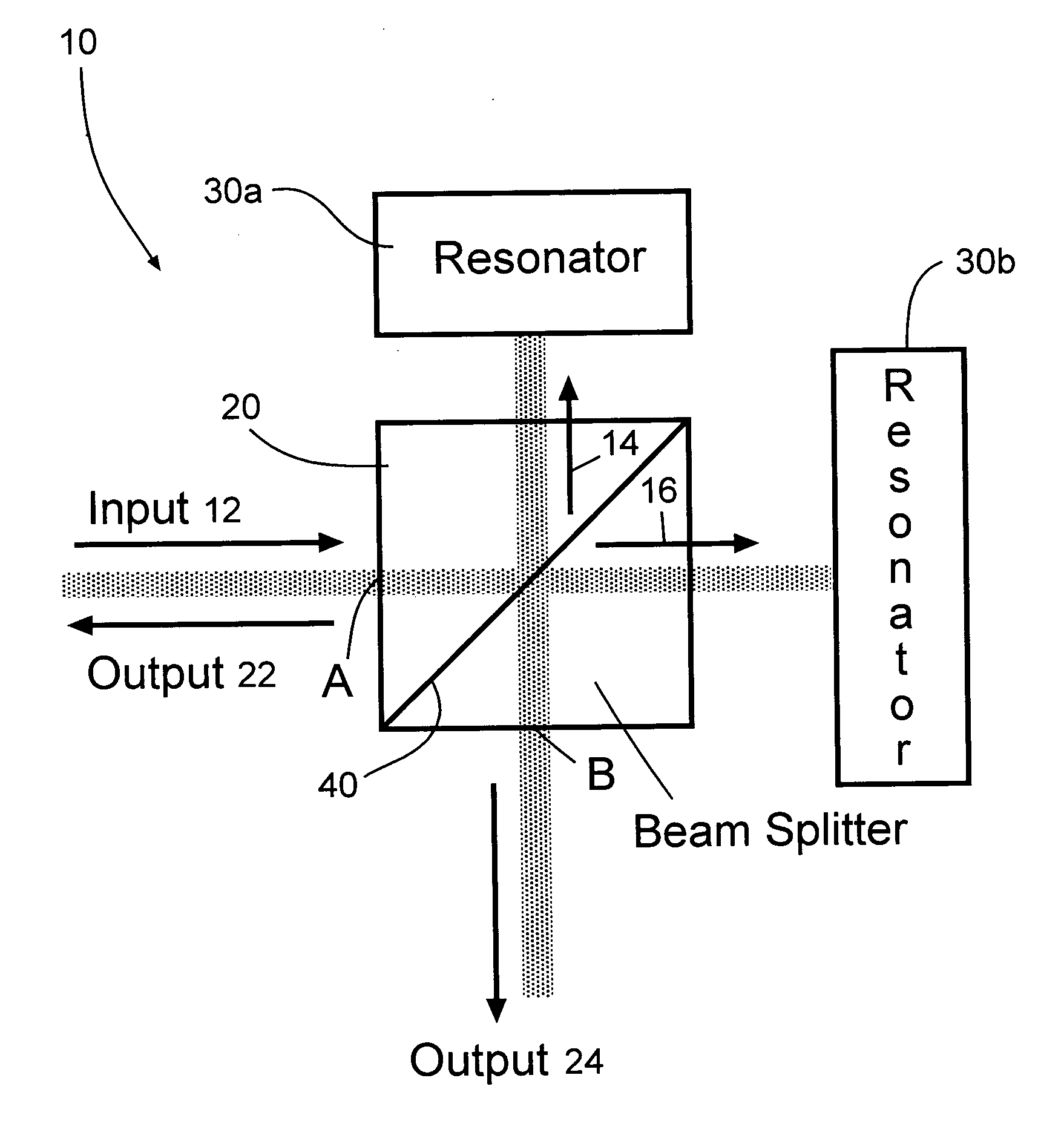
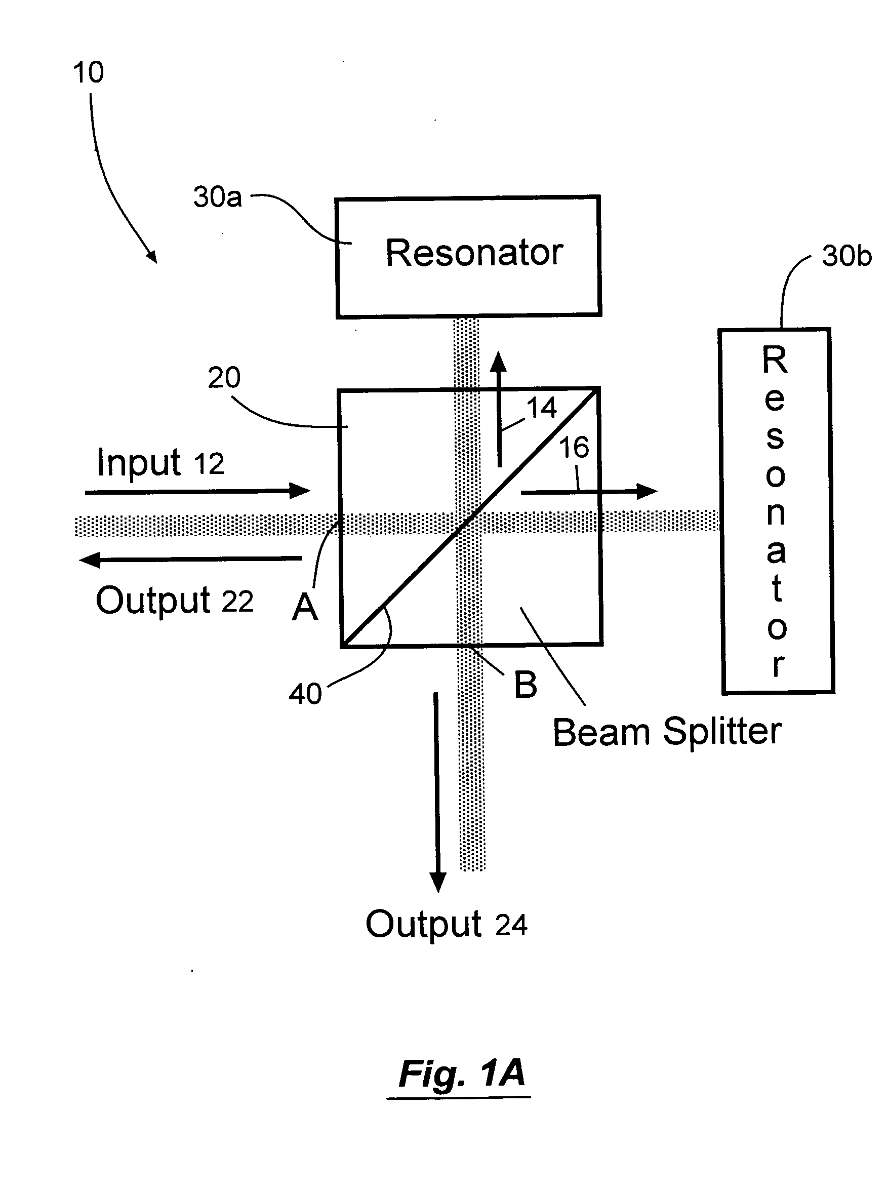
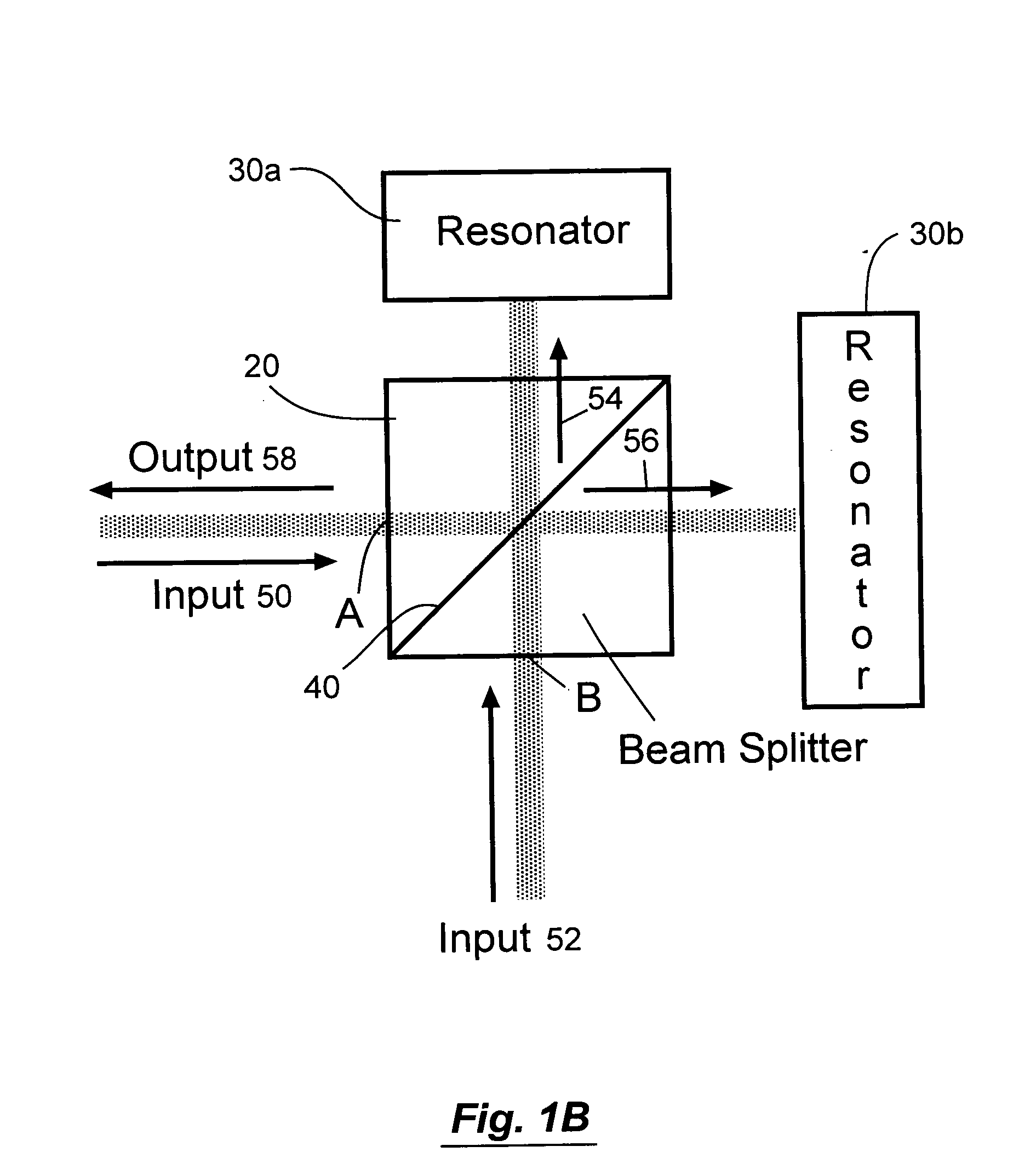
An optical wavelength router includes a beamsplitter, a first resonator, and a second resonator. The beamsplitter separates an input signal into a first beam and a second beam. The first resonator reflects the first beam and has a partially reflective front surface and a highly reflective back surface spaced a first optical thickness from the front surface. The second resonator reflects the second beam and has a partially reflective front surface and a highly reflective back surface spaced a second optical thickness from the front surface. The difference between the optical thicknesses of the first and second resonators is approximately equal to one-eighth wavelength.

Description

FIELD OF THE INVENTION The present invention relates generally to the field of optical communications systems. More specifically, the present invention relates to a dispersion compensated optical wavelength router and cascaded architectures. BACKGROUND OF THE INVENTION Wavelength division multiplexing is a commonly used technique that allows the transport of multiple optical signals, each at a slightly different wavelength, over an optical fiber. The ability to carry multiple signals on a single fiber allows that fiber to carry a tremendous amount of traffic, including data, voice, and digital video signals. For example, the International Telecommunications Union (ITU) Draft Recommendation G.mcs proposes a frequency grid which specifies various channel spacings including 100 GHz and 200 GHz. It would be advantageous to obtain smaller channel spacings. As transmission systems evolve to longer distances, smaller channel spacings, and higher bit rates, however, the phenomenon of disp...

Claims


Application Information

Patent Timeline
IPC IPC(8): G02B6/34H04J14/02H04J14/06
CPCG02B6/272G02B6/2746G02B6/29302G02B6/29349H04J14/06G02B6/29386H04J14/02H04J14/0208H04J14/0213G02B6/29358
Inventor ZHOU, GANLIN, SIHAN
Owner EC OPTICS TECH
Features
  • Generate Ideas
  • Intellectual Property
  • Life Sciences
  • Materials
  • Tech Scout
  • Unparalleled Data Quality
  • Higher Quality Content
  • 60% Fewer Hallucinations
Learn More