Method for knee-joint surgery

a knee joint and joint replacement technology, applied in the field of knee joint replacement surgery, can solve the problems of cartilage loss pain and stiffness,

Inactive Publication Date: 2005-02-03
MINNESOTA SCI
View PDF41 Cites 4 Cited by
  • Summary
  • Abstract
  • Description
  • Claims
  • Application Information

AI Technical Summary

Problems solved by technology

As the cartilage is worn away, the tibia and femur rub against each other which causes pain and stiffness.
The second type of arthritis is rheumatoid arthritis which causes the synovial membrane to become thickened and inflamed, producing excessive amounts of synovial fluid which over-fills the joint space.
The chronic inflammation can d

Method used


Image

  • Method for knee-joint surgery
  • Method for knee-joint surgery
  • Method for knee-joint surgery

Examples


Embodiment Construction

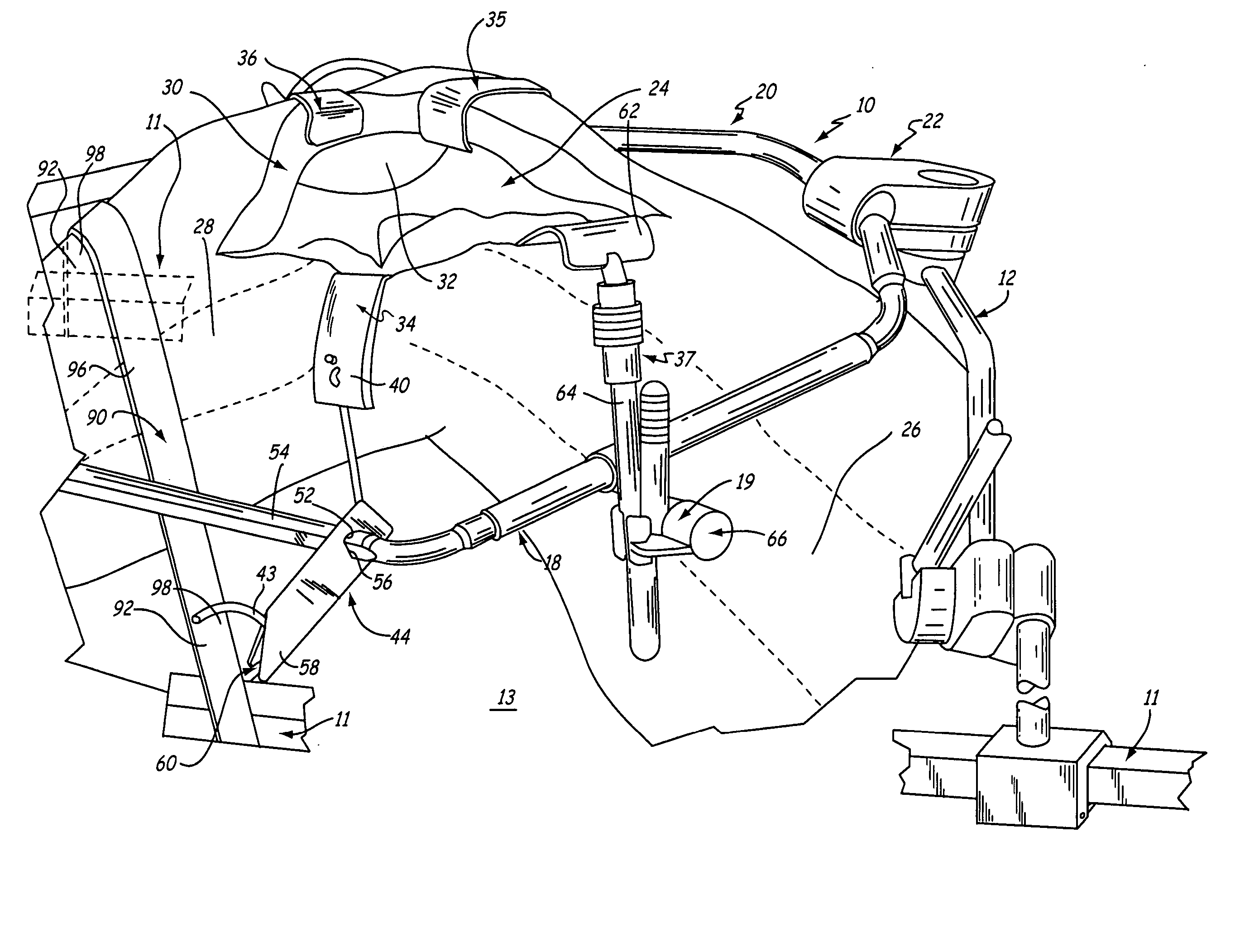
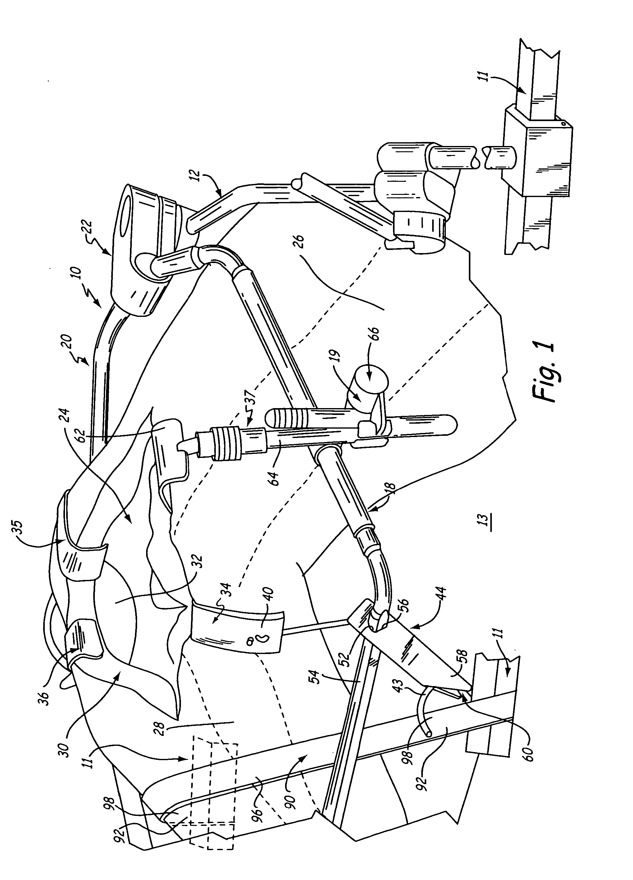
[0018] The present invention includes a method for performing knee-joint replacement surgery that utilizes surgical retractors that are secured to a retractor support apparatus that is mounted to a surgical table. Preferably, the knee-joint replacement surgery is performed in a manner that does not require repositioning of the surgical retractors within the incision or re-securing the surgical retractors to the support apparatus during the surgical procedure.

[0019] The apparatus used in the knee-joint replacement surgery of the present invention is generally indicated at 10 in FIG. 1. The apparatus 10 includes a retractor support apparatus 12 that is rigidly mounted to a rail 11 of a surgical table 13 in a manner that is well known in the art and is described in U.S. Pat. Nos. 4,617,916, 4,718,151, 4,949,707, 5,400,772, 5,741,210, 6,042,541, 6,264,396 and 6,315,718 all of which are herein incorporated by reference. From the mount to the surgical table 13, the retractor support appa...


PUM


Abstract

A method of performing knee-joint surgery includes positioning the tibia and the femur such that the knee-joint is disposed in a bent position. An incision is made to expose the knee-joint. A retractor support is mounted to a surgical table. The skin and flesh layers proximate the knee-joint are retracted utilizing a retractor that is attached to the retractor support which is mounted to a surgical table.

Description

CROSS REFERENCE TO RELATED APPLICATIONS [0001] This application is a continuation-in-part of application Ser. No. 10 / 623,179; filed Jul. 18, 2003, which is hereby incorporated by reference in its entirety, which claims priority of U.S. Provisional Application No. 60 / 396,850, filed Jul. 18, 2002, the content of which is hereby incorporated by reference in its entirety. [0002] This application is also a continuation-in-part of application Ser. No. 10 / 728,202 filed on Dec. 4, 2003, which is hereby incorporated by reference in its entirety, which is a continuation of application Ser. No. 10 / 077,693, filed Feb. 15, 2002, which is incorporated by reference in its entirety, which is a continuation of application Ser. No. 09 / 990,420 filed on Nov. 21, 2001, which is incorporated by reference in its entirety, and resulting in U.S. Pat. No. 6,368,271.BACKGROUND OF THE INVENTION [0003] The present invention relates to a method for performing knee-joint replacement surgery. More particularly, th...

Claims


Application Information

Patent Timeline
IPC IPC(8): A61B1/32
CPCA61B17/02A61B2017/0287A61B17/0293
Inventor LEVAHN, STEVEN M.BALLANTINE, ROBERTSHARRATT, TODD W.
Owner MINNESOTA SCI
Why Eureka
Try Eureka