Battery cooling system for vehicle
a battery cooling and vehicle technology, applied in the field of battery cooling systems, can solve the problems of restricting the temperature inside the passenger compartment from being increased, the cooling capacity of the passenger compartment by the air conditioner is not reduced, etc., and achieves the effect of reducing the compression capacity of the compression device, reducing the cooling capacity of the passenger compartment, and accurately controlling the operation of the compressor
- Summary
- Abstract
- Description
- Claims
- Application Information
AI Technical Summary
Benefits of technology
Problems solved by technology
Method used
Image
Examples
first embodiment
[0032] (First Embodiment)
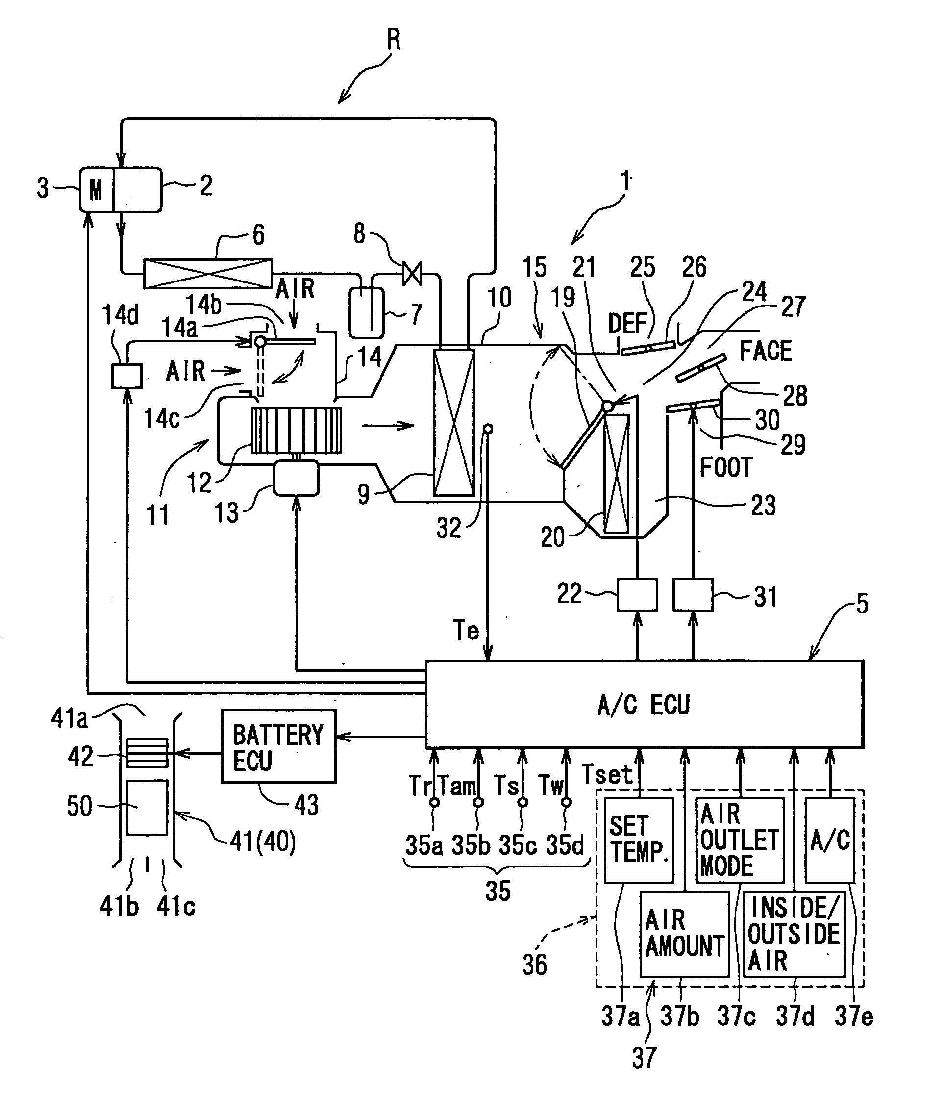
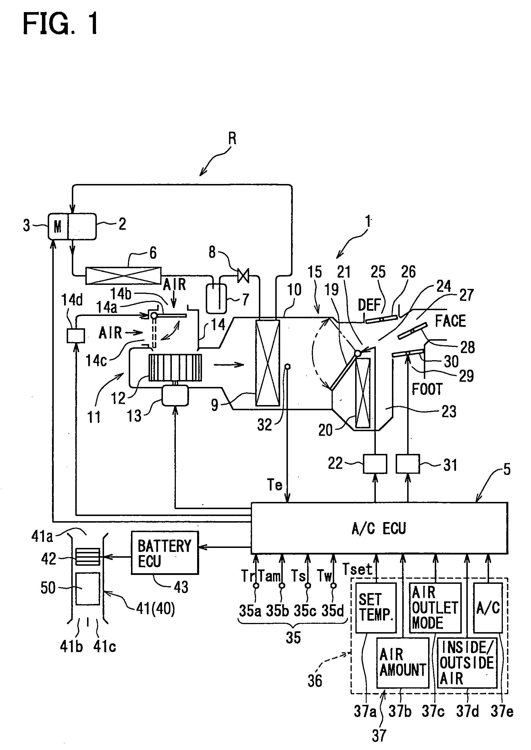
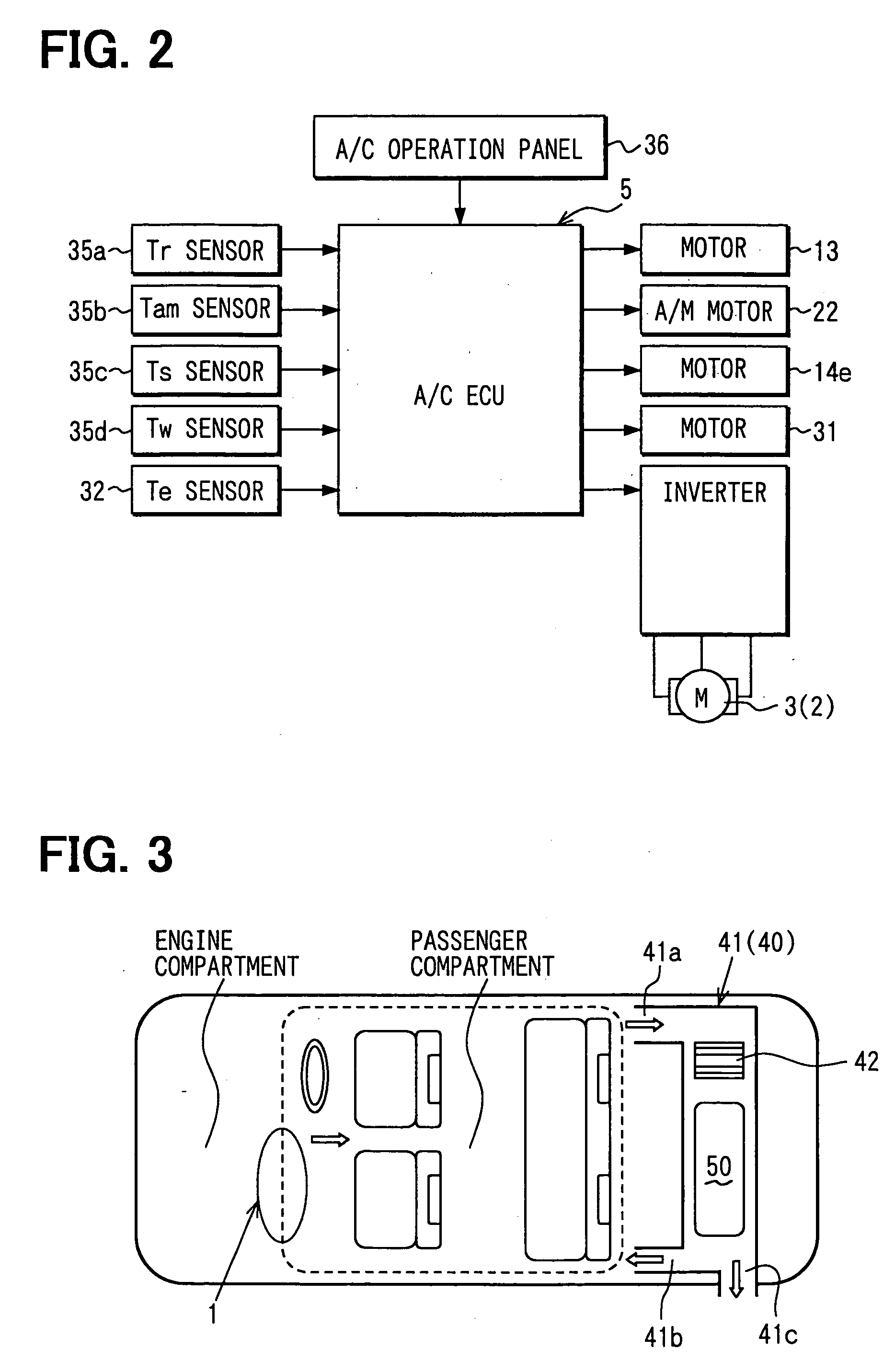
[0033] The first embodiment of the present invention will be now described with-reference to FIGS. 1-11. As shown in FIG. 1, a vehicle air conditioner 1 includes a refrigerant cycle R that is provided with an electrical compressor 2 for sucking and compressing refrigerant and for discharging the compressed refrigerant. The electrical compressor 2 is integrated with an electrical motor 3 to be operated by electrical power of the electrical motor 3. Therefore, a rotation speed (compression capacity) of the electrical compressor 2 is changed by changing the rotation speed of the electrical motor 3. The rotation speed of the electrical motor 3 is controlled by an air conditioning ECU 5 so as to control the compression capacity (cooling capacity) of the electrical compressor 2.
[0034] High-temperature and high-pressure gas refrigerant discharged from the electrical compressor 2 flows into a condenser 6 (high-pressure heat exchanger, refrigerant radiator), and is ...
second embodiment
[0069] (Second Embodiment)
[0070] The second embodiment of the present invention will be now described with reference to FIG. 12. In the above-described first embodiment, the inside air temperature Tr is compared with the first predetermined inside air temperature at step S23, and the upper limit rotation speed IVOmax is decreased to the second predetermined value. IV02 at step S25b after the predetermined time t1 passes after the air amount to be blown to the battery 50 is increased. However, in the second embodiment, at step S231 in FIG. 12, it is determined whether or not the inside air temperature Tr is larger than a second predetermined inside air temperature Tr2 that is lower than the first predetermined inside air temperature Tr1. Further, at step S25 in FIG. 12, when the target air temperature TAO is equal to or higher than the first predetermined target temperature TAO1 or when the inside air temperature Tr is equal to or lower than the second predetermined inside air temper...
third embodiment
[0074] (Third Embodiment)
[0075] The third embodiment of the present invention will be now described with reference to FIG. 13. In the third embodiment, step S231 of the second embodiment shown in FIG. 12 is changed to step S232 in FIG. 13. In the third embodiment, the other parts are the same as that described in the second embodiment.
[0076] In the third embodiment, at step S232, when the inside air temperature Tr is reduced by a predetermined temperature AT from the first predetermined inside air temperature Tr1 at step S232, the upper limit rotation speed of the compressor 2 is reduced at step S25 so that the cooling capacity of the compressor 2 is reduced.
[0077] According to the third embodiment, even when the inside air temperature Tr is equal to or lower than the first predetermined inside air temperature Tr1, the upper limit rotation speed is not reduced to the second predetermined valve IV02. When the inside air temperature Tr is further reduced by the predetermined tempera...
PUM
 Abstract
Description
Claims
Application Information
 - R&D
- Intellectual Property
- Life Sciences
- Materials
- Tech Scout
- Unparalleled Data Quality
- Higher Quality Content
- 60% Fewer Hallucinations
Browse by: Latest US Patents, China's latest patents, Technical Efficacy Thesaurus, Application Domain, Technology Topic, Popular Technical Reports.
© 2025 PatSnap. All rights reserved.Legal|Privacy policy|Modern Slavery Act Transparency Statement|Sitemap|About US| Contact US: help@patsnap.com


