
Image encoding device, image decoding device, electronic camera and recording medium

a technology of image encoding and decoding, which is applied in the field of image encoding devices, can solve the problems of heavy processing burden, heavy processing burden, and complex implementation of the roi processing system, and achieve the effects of reducing the processing time required for encoding the image into the selected region and non-selected region, reducing the processing time inside the electronic camera, and reducing the processing tim

Active Publication Date: 2005-05-10
NIKON CORP
View PDF9 Cites 5 Cited by
  • Summary
  • Abstract
  • Description
  • Claims
  • Application Information

AI Technical Summary

Benefits of technology

[0018]An object of the present invention is to accomplish the division into the selected region and non-selected region that is performed at the time of image encoding with a smaller processing burden.
[0020]Furthermore, another object of the present invention is to accomplish the division into the selected region and non-selected region that is performed at the time of image decoding with a smaller processing burden.
[0031]In a first embodiment of the present invention, numerical equation data that stipulates the boundaries of the selected region is subjected to an equation evaluation, and a judgement is made as to whether the transformation coefficients belong to the selected regions. As a result several advantages are obtained. The quantity of the numerical equation data does not vary even if the numbers of vertical and horizontal pixels of the image increase. Accordingly, in the ROI processing system, it is necessary only to handle numerical equation data in which the quantity of data is substantially fixed, so that the implementation of the ROI processing system can be simplified compared to conventional examples in which a mask image in which the quantity of data varies is handled by buffering. Numerical equation data can also be quickly applied to images in which the numbers of vertical and horizontal pixels differ by performing a simple coordinate transformation. Accordingly, since the trouble of preparing a mask image, etc. each time that the numbers of vertical and horizontal pixels of the image change is eliminated, the processing burden is correspondingly reduced compared to conventional examples. The quantity of numerical equation data is generally smaller than the quantity of data in a mask image. Accordingly, the burden of data holding in the ROI processing system can be reduced compared to conventional examples in which a mask image is handled. Furthermore, the burden of transmitting data to the ROI processing system can also be reduced.
[0032]Furthermore, as a result of the present invention numerical equation data can be applied to a plurality of sub-band split regions by performing a simple coordinate transformation. Accordingly, in the present invention, the trouble of converting the resolution of the mask image in accordance with the number of samples, which occurs in conventional examples, does not arise. In the present invention, as a result of a synergistic effect of these advantages, the processing burden of the division into the selected region and non-selected region that is performed during encoding of the image can be appropriately reduced.
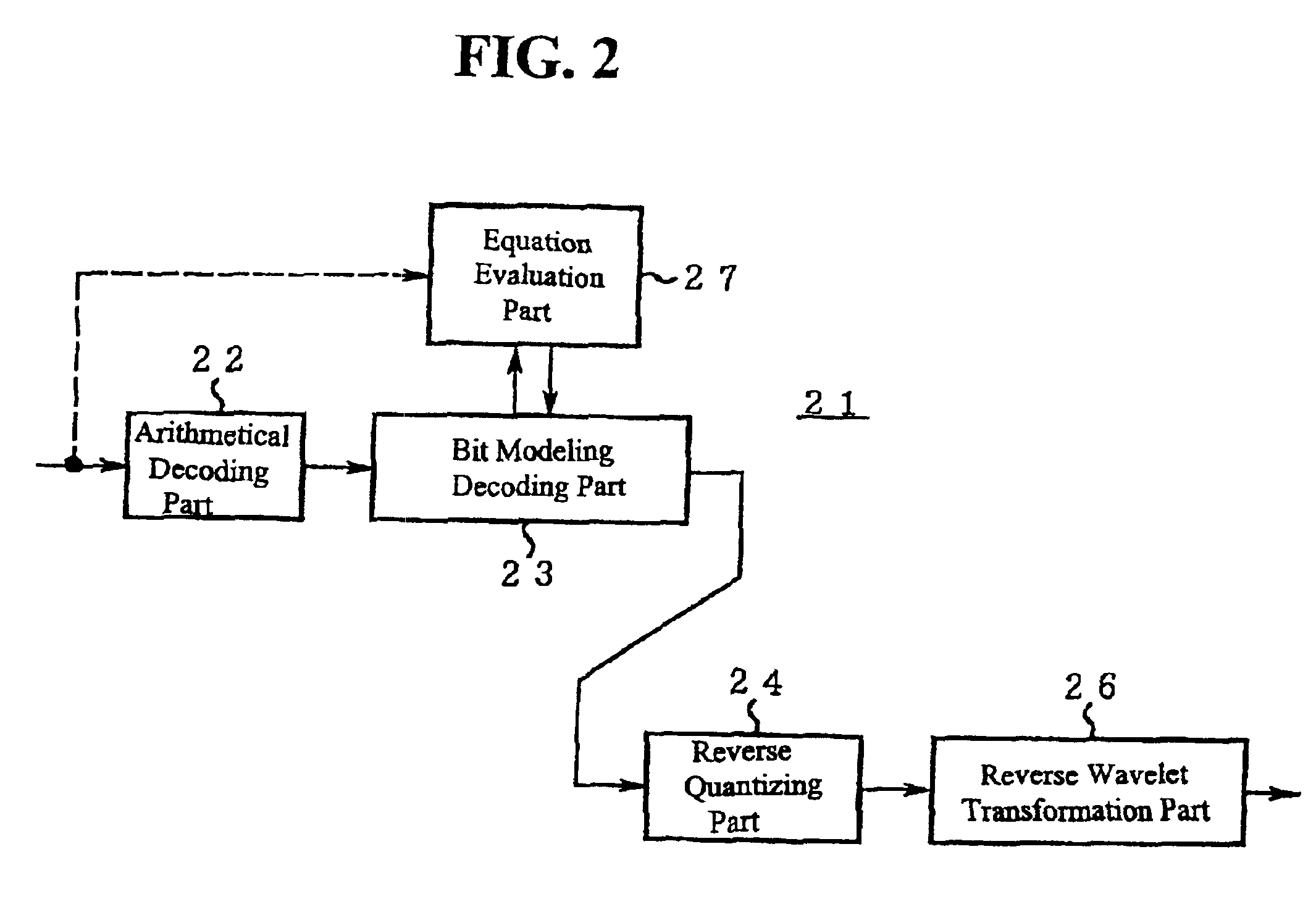
[0037]Meanwhile, in the image decoding device of another embodiment, the division into the selected region and non-selected region is performed using numerical equation data in the file. In this case, the determination of the selected region can be accurately performed under the same conditions as in the image encoding device.
[0038]The electronic camera of the present invention is equipped with the image encoding device described in any of the previous embodiments. Accordingly, the processing time required for division into the selected region and non-selected region during encoding of the image can be appropriately reduced. As a result, the image processing time inside the electronic camera can be shortened compared to that required in conventional examples, so that an electronic camera that is easier to use can be realized.

Problems solved by technology

As a result, the following problem arises: in the ROI processing system, the mask image with a variable quantity of data must be handled by buffering, so the implementation of the ROI processing system becomes complicated.
Furthermore, each time that the numbers of vertical and horizontal pixels of the image are varied, a mask image must be newly prepared, which results in a heavy processing burden.
Moreover, since the mask image has a large quantity of data, the burden of transferring the mask image to the ROI processing system and the burden of storing the mask image as data also are heavy.
Accordingly, the mask image must be enlarged or reduced in accordance with each sub-band split region, so that the burden of calculating the resolution conversion also is heavy.

Method used


Image

  • Image encoding device, image decoding device, electronic camera and recording medium
  • Image encoding device, image decoding device, electronic camera and recording medium
  • Image encoding device, image decoding device, electronic camera and recording medium

Examples


Embodiment Construction

[0052]Reference will now be made in detail to the preferred embodiments of the present invention, examples of which are illustrated in the accompanying drawings.

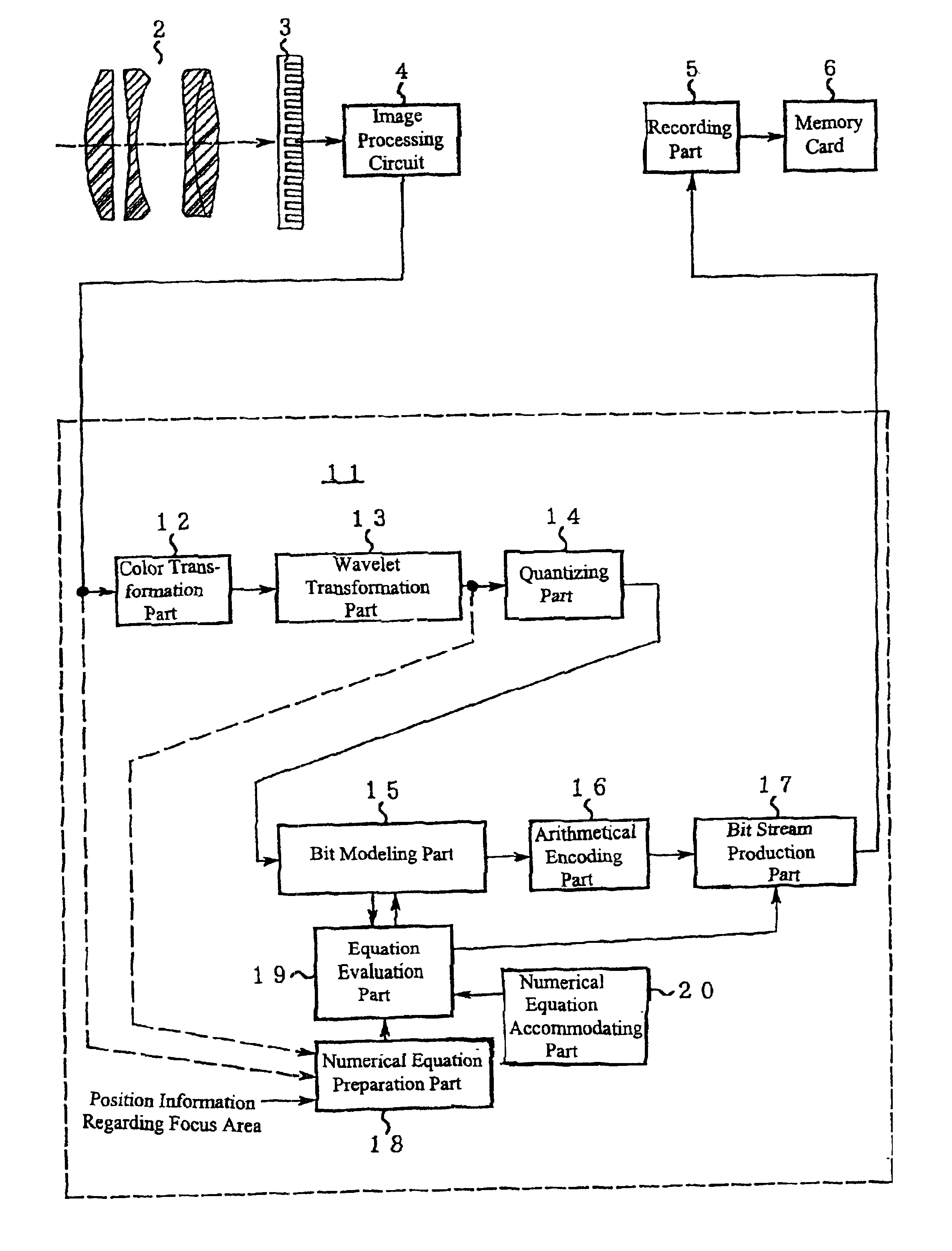
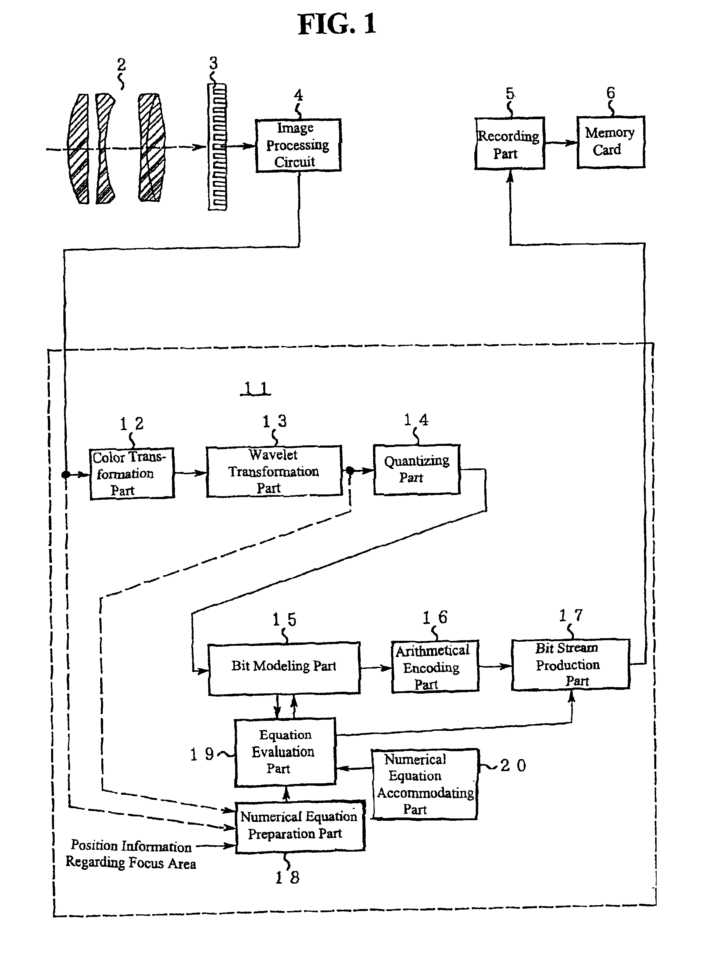
[0053]FIG. 1 is a block diagram which illustrates the construction of the electronic camera 1 and image encoding device 11. In FIG. 1, an imaging lens 2 is mounted in the electronic camera 1. The light-receiving plane of an imaging element 3 is disposed in the image space of this imaging lens 2. The image data produced by the imaging element 3 is subjected to A / D conversion and color interpolation processing, etc., via an image processing circuit 4, and is then sent to the image encoding device 11. The compressed image file output from this image encoding device 11 is sent to a recording part 5. The recording part 5 records this compressed image file on a memory card 6.

[0054]Next, the internal construction of the above-mentioned image encoding device 11 will be described. The image data input into the image encoding device 1...


PUM


Abstract

An image encoding device equipped with a transformation component which transforms given image data into transformation coefficients by subjecting this image data to a frequency decomposition, a dividing component which divides the transformation coefficients produced by the transformation component into a selected region on the image and a non-selected region other than the selected region, and an encoding component which encodes the transformation coefficients by preferentially allocating a greater quantity of information to the selected region than to the non-selected region, and the dividing component performs an equation evaluation of numerical equation data that stipulates the boundary of the selected region, and determines whether the transformation coefficients belong to the selected region on the basis of the results of this equation evaluation, to perform the division into a selected region and non-selected region during image encoding with less processing.

Description

[0001]The present invention claims the benefit of Japanese Patent Application No. 2000-390837 filed in Japan on Dec. 22, 2000, which is hereby incorporated by reference.BACKGROUND OF THE INVENTION[0002]The present invention relates to an image encoding device, and more particularly to an image encoding device which encodes image data, an image encoding program and a recording medium for the same. The present invention also relates to an image decoding device which decodes a compressed image file, an image decoding program, and a recording medium for the same, and an electronic camera which is equipped with an image encoding device.DISCUSSION OF THE RELATED ART[0003]Encoding algorithms and encoding processing is known in the art. For example the JPEG2000 encoding algorithm and encoding processing is an encoding procedure that includes: Color Coordinate Transformation, Wavelet Transformation, Quantization, Bit Modeling, ROI (Region of Interest) function, and Arithmetical Encoding of t...

Claims


Application Information

Patent Timeline
Patent Type & Authority Patents(United States)
IPC IPC(8): G06T9/00H04N7/26G03B19/02H03M7/30H04N1/41H04N1/413H04N5/225H04N11/04H04N19/122H04N19/132H04N19/14H04N19/167H04N19/169H04N19/182H04N19/186H04N19/196H04N19/33H04N19/34H04N19/36H04N19/60H04N19/63H04N19/91H04N101/00
CPCH04N19/647H04N19/63H04N19/17H04N19/127H04N19/146H04N19/115
Inventor OKADA, SADAMI
Owner NIKON CORP
Learn More