Filter head and burner system incorporating same

a burner system and filter head technology, applied in the direction of moving filter element filters, filtration separation, separation processes, etc., can solve the problems of all the oil contained in the tank leakage location, all the oil from the tank will leak into the home or building, and is particularly troublesome for residential and commercial buildings. , to achieve the effect of reducing the number of different connections, reducing the likelihood of leakage, and reducing the cost of installation

Inactive Publication Date: 2005-02-10
SUNTEC INDS
View PDF3 Cites 9 Cited by
  • Summary
  • Abstract
  • Description
  • Claims
  • Application Information

AI Technical Summary

Benefits of technology

[0007] It is an advantage of the present invention that only a single unit needs to be mounted along a fluid plumbing line of a burner to provide for both safety valve and filter mounting functions. This reduces the cost to install a filter head and safety valve in a system and also reduces the number of different connections needed which can reduce the likelihood for leakage occurring.
[0008] The present invention is also directed toward an oil burner system incorporating the filter head as described above which includes the filter head interposed between an oil tank and an oil burner that has an oil pump that is adapted to pump fuel to the combustion chamber of the oil burner.
[0009] Other aspects, objectives and advantages of the invention will become more apparent from the following detailed description when taken in conjunction with the accompanying drawings.

Problems solved by technology

A problem with gravity fed installations or other types of installations described in the aforementioned literature is that if there is a leak in the oil line, all of the oil contained in the tank can leak out through the leakage location(s).
This can be particularly troublesome in residential and commercial buildings where the line leads to a burner on a furnace or boiler.
In particular, with the oil line running into the house or building, all of the oil from the tank will leak into the home or building if the leak occurs along the line within the house or building.

Method used


Image

  • Filter head and burner system incorporating same
  • Filter head and burner system incorporating same
  • Filter head and burner system incorporating same

Examples


Embodiment Construction

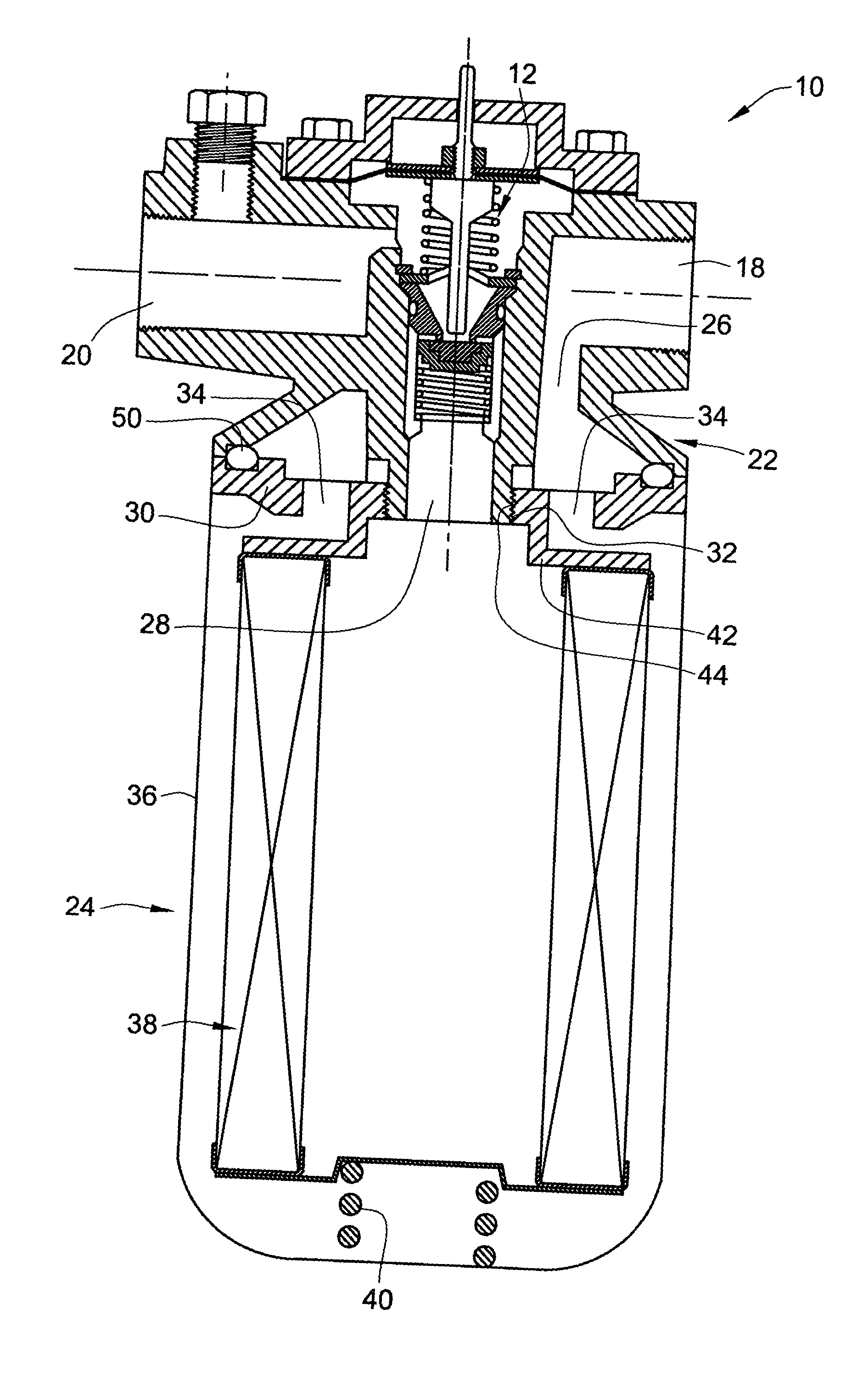
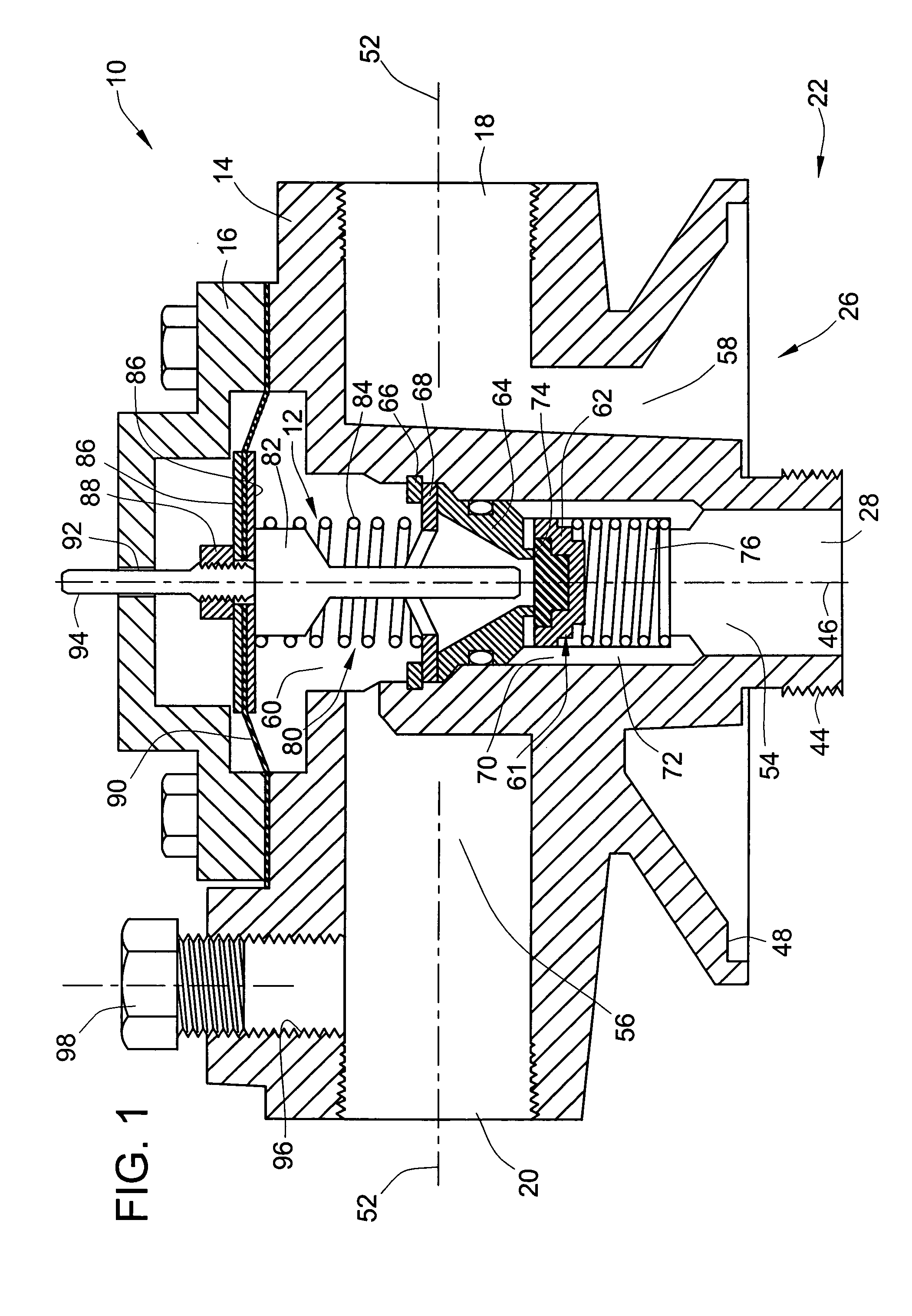
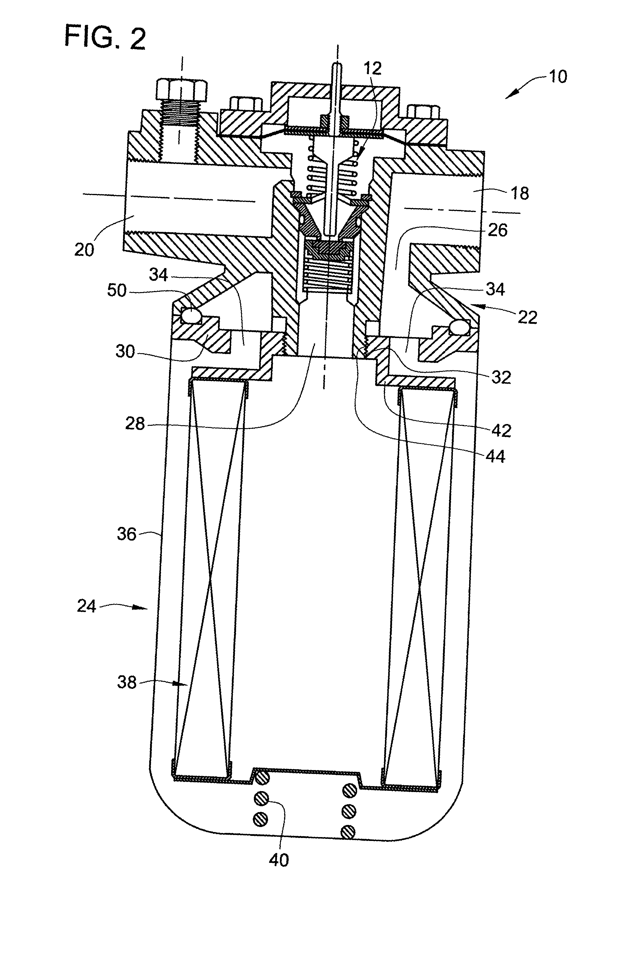
[0013] Referring to FIG. 1, an embodiment of the present invention has been disclosed as a filter head 10 that integrally includes a safety valve 12. The filter head 10 generally includes a filter housing which as shown may comprise a filter head body 14 and a cover plate 16. These components can be made of cast metal material and / or can also be machined.

[0014] The filter head body 14 comprises a main threaded inlet port 18 for receiving fuel oil from a tank or booster pump and a main threaded outlet port 20 for outletting oil to a burner. The inlet and outlet ports 18 and 20 provide means for mounting the filter head to external plumbing lines such as might be used in the oil burner system shown in FIG. 3. The filter head body 14 also integrally provides a filter mounting stub 22 that facilitates mounting of a filter cartridge 24 fluidically between the inlet and outlet ports 18 and 20. To provide for fluid communication with the filter cartridge, the filter mounting stub includes...


PUM

PropertyMeasurementUnit
vacuum pressureaaaaaaaaaa
gravityaaaaaaaaaa
pressureaaaaaaaaaa

Abstract

The present invention is directed toward a filter head that is adapted to mount a filter between an upstream fluid supply and a downstream fluid pump such as might be used for an oil burner system that includes a combination of the filter head and the safety valve in a single unit that may be interposed at a location along an oil conduit. The filter head comprises a filter head housing having an inlet port and an outlet port and a filter mounting stub that is adapted to mount the filter thereto. The filter mounting stub provides a filter head entrance port and a filter head exit port fluidically between the inlet and the outlet ports for communication with the filter when mounted thereto. A safety valve is mounted in the filter head housing and is arranged fluidically between the inlet and outlet port of the filter head housing. The safety valve has open and closed positions and opens in response to vacuum pressure at the outlet port.

Description

FIELD OF THE INVENTION [0001] The present invention pertains generally to filter mounting heads and safety valves in oil burner systems or other fluid systems. BACKGROUND OF THE INVENTION [0002] As is disclosed in Model PRV-38 Oil Safety Valve Installation Information available from Suntec Industries, Inc., an oil burning system in its basic form typically includes an elevated tank that feeds fuel oil via gravity through a filter which is mounted along the oil conduit passageway via a filter mounting head to an oil burner which includes an oil pump such as any of those models manufactured and sold by Suntec Industries, Inc. The filter is arranged along the oil feed line and is mounted thereto with a filter mounting head to filter out and prevent contaminants from reaching the oil pump or burner. [0003] A problem with gravity fed installations or other types of installations described in the aforementioned literature is that if there is a leak in the oil line, all of the oil containe...

Claims


Application Information

Patent Timeline
Patent Type & Authority Applications(United States)
IPC IPC(8): B01D35/147
CPCB01D2201/302B01D35/147
Inventor BUHL, MICHAEL E.HUNSBERGER, DALE L.ZIERKE, DAVIDMITCHELL, BILL
Owner SUNTEC INDS
Why Eureka
Try Eureka