Sensor array with a number of types of optical sensors

a technology of optical sensors and arrays, applied in the field of sensor arrays, can solve the problems of increasing the space required on the sensor array for pixel space, and characters appearing on traffic signs and information boards cannot be displayed in recognizable manner on images produced by night vision devices, and achieve the effect of high local resolution

Inactive Publication Date: 2005-02-10
DAIMLER AG
View PDF8 Cites 33 Cited by
  • Summary
  • Abstract
  • Description
  • Claims
  • Application Information

AI Technical Summary

Benefits of technology

[0006] It is the task of the present invention to provide a sensor array with which images of a scene can be produced from combined infrared and color information, which makes possible a high local resolution with small dimensions of the sensor array.
[0009] In the inventive sensor array the known effect is employed, whereby the human eye reacts approximately with ten times the sensitivity to changes in light intensity than to changes in color. That is, an observer does not detect any changes in quality between two images, of which in one the light intensity and color intensity both have high resolution, and a second, in which only the light intensity has a high resolution, and the chromatic resolution is significantly lower.
[0011] When however the light intensity of the combined image to be produced depends only upon the infrared detected light intensity, then it is sufficient, when the sensor array detects the colors of a scene with a lower resolution than it detects light intensity in the infrared. As a consequence, by omitting unnecessary sensors for the visible spectral range, the comprehensiveness of the sensor array necessary for a given pixel count or number can be reduced or, as the case may be, with a specified dimension of the sensor array the resolution that can be achieved can be improved.

Problems solved by technology

Characters appearing on traffic signs and information boards thus cannot be displayed in recognizable manner on images produced by night vision devices.
Thereby the problem occurs, that as the number of sensors necessary for display of a pixel increases, the space required on the sensor array for the pixel also increases.

Method used


Image

  • Sensor array with a number of types of optical sensors
  • Sensor array with a number of types of optical sensors
  • Sensor array with a number of types of optical sensors

Examples


Embodiment Construction

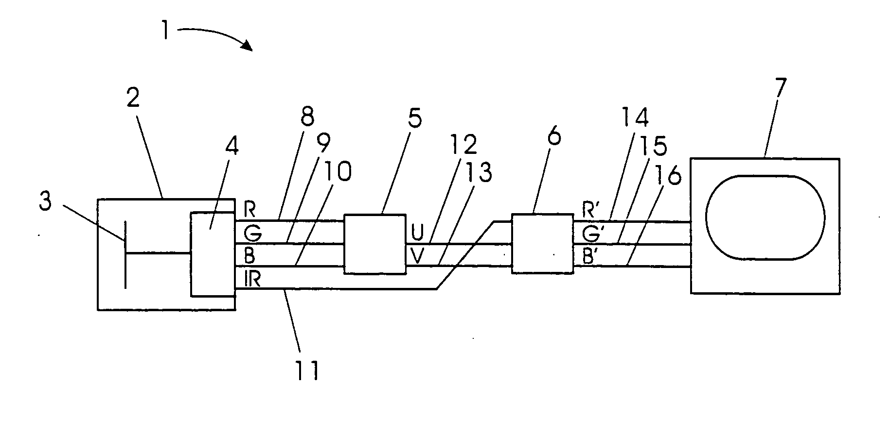
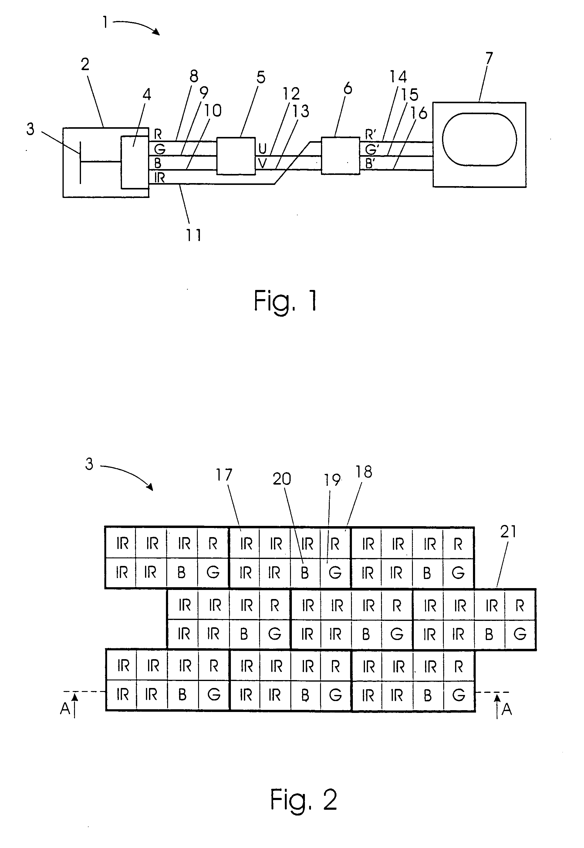
[0026] An inventive image reproduction system 1 is shown in simplified form in FIG. 1. The image reproduction system 1 includes a camera 2 with sensor array 3 and associated electronics 4, a first matrix 5, a second matrix 6 and a monitor 7. From the camera 2 an R-video channel 8, a G-video channel 9 and a B-video channel run to matrix 5. An IR-video channel 11 runs from the camera 2 to matrix 6. Further, a U-video channel 12 and a V-video channel 13 run from matrix 5 to matrix 6. From the matrix 6 an R′-video channel 14, a G′-video channel 15 and B′-video channel 16 run to monitor 7.

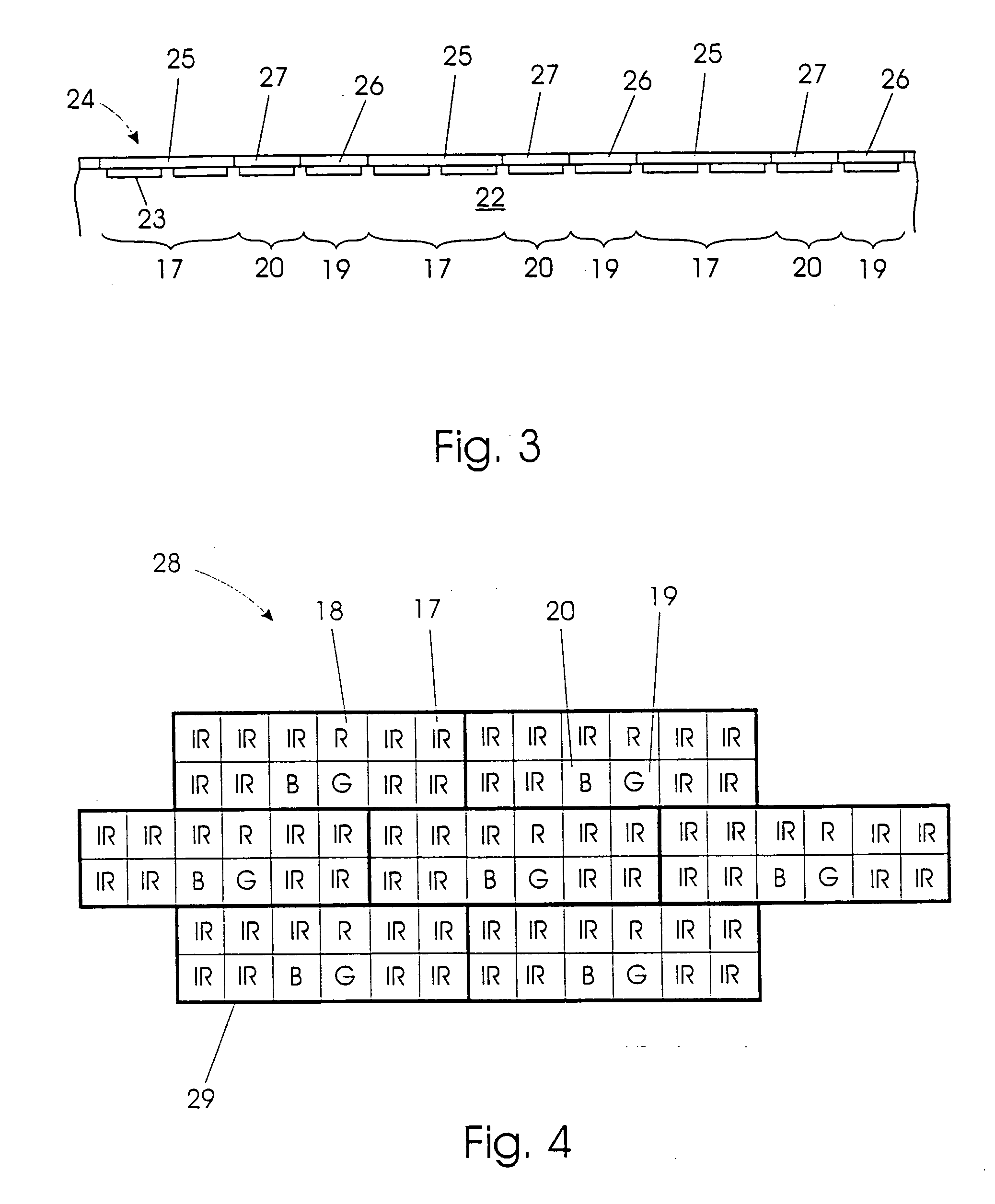
[0027]FIG. 2 shows a basic design of a segment of the sensor array 3. This includes IR-sensors 17 for detection of radiation in an infrared spectral range, R-sensors 18 for detection of light in a red wavelength range, G-sensors 19 for detection of light in a green wavelength range and B-sensors 20 for detection of light in a blue wavelength range. Respectively eight sensors 17, 18, 19, 20 form a group...


PUM


Abstract

Disclosed is a sensor array (3, 28) with a number of sensors (17, 18, 19, 20) arranged in periodic groups (21, 29, 30) for detection of electro-magnetic radiation, including sensors (17) of a first type for detection of radiation in an infrared spectral range and sensors (18, 19, 20) of at least a second type for detection of light in a visible spectral range. In each group (21, 29, 30) the number of sensors (17) of the first type exceeds the number of sensors (18, 19, 20) of the second type. Also disclosed is a camera (2) with such a sensor array (3, 28) as well as an image reproduction system (1) with such a camera (2) and a vehicle with such an image reproduction system (1).

Description

BACKGROUND OF THE INVENTION [0001] 1. Field of Invention [0002] The invention concerns a sensor array with a number of sensors, arranged in periodic groups, for detection of electromagnetic radiation, including sensors of a first type for detection of radiation in an infrared spectral region and sensors of at least a second type for detection of light in a visible spectral region. The invention also concerns a camera with such a sensor array, as well as an image rendering system involving such a camera, and a vehicle with such an image rendering system. The inventive sensor array is suitable for employment in night vision devices, in particular vehicle night vision devices. [0003] 2. Related Art of the Invention [0004] Currently, such night vision devices are being increasingly employed in motor vehicles in order to make it possible for the vehicle operator to maintain orientation in darkness and to facilitate recognition of objects. Night vision devices include sensors for detectio...

Claims


Application Information

Patent Timeline
Patent Type & Authority Applications(United States)
IPC IPC(8): H04N5/33H04N7/18H04N9/04
CPCH04N5/33H04N9/045H04N5/332H04N23/11H04N25/131H04N25/135
Inventor EGGERS, HELMUTHKURZ, GERHARDSEEKIRCHER, JUERGENWOHLGEMUTH, THOMAS
Owner DAIMLER AG
Why Eureka
Try Eureka