Brushless DC motor and method of manufacturing brushless DC motor

a brushless dc motor and motor technology, applied in the direction of dynamo-electric machines, magnetic circuit rotating parts, magnetic circuit shapes/forms/construction, etc., can solve the problems of unavoidable torque pulsation, small cogging torque pulsation, and sacrifice of motor efficiency, so as to eliminate cogging torque

Inactive Publication Date: 2005-02-10
KOYO SEIKO CO LTD
View PDF8 Cites 13 Cited by
  • Summary
  • Abstract
  • Description
  • Claims
  • Application Information

AI Technical Summary

Benefits of technology

It is an object of the present invention to provide a brushless DC motor capable of effectively eliminating cogging torque.
A method of manufacturing a brushless DC motor according to the nineteenth aspect is a method of manufacturing a brushless DC motor of any one of the first through fourth aspects, wherein the permanent magnets of the rotor are produced by magnetizing the rotor blocks or rotor by using the stator as a magnetic yoke after assembling the motor. Accordingly, it is possible to eliminate a difficult handling work caused by the permanent magnets being attracted to the stator, case, etc. and prevent dust such as an iron powder attracted to permanent magnets from being carried into the case, thereby enabling the manufacturing of a brushless DC motor having good quality.

Problems solved by technology

In the brushless DC motor, torque pulsation, i.e., cogging torque, is unavoidably produced because of the presence of slots for winding in the stator and the presence of permanent magnets in the rotor.
In an actual brushless DC motor, it is possible to significantly improve the pulsation period of cogging torque by the above-mentioned method, but there is a problem that small cogging torque pulsation remains.
However, the motor efficiency is sacrificed.
Even if the pulsations of such cogging torque waveforms are combined while displacing them by an amount corresponding to the half period θ12 of the pulsation period θ11, there is a problem that the pulsation of cogging torque as shown in FIG. 4B still remains.
It is apparent from the expression (1) that, in the brushless DC motor comprising the rotor divided into two blocks, the fundamental wave components of cogging torques cancel each other out and are thus eliminated, but there is a problem that the even harmonics components remain.
However, both of the conventional techniques shown in FIGS. 5 and 6 suffer from problems including poor magnetic efficiency.
Moreover, it is necessary to perform various analysis and trial manufacture to determine the shape of the permanent magnets 107 or the outer circumference of the rotor core 106, resulting in high development costs.
Furthermore, it is necessary to process the small configurations accurately, and thus the processing itself is difficult.
Nevertheless, an objective to reduce the cogging torque is not sufficiently achieved.
In particular, when strong rare-earth based permanent magnets are used to meet the demand for a reduction in size as in recent years, the cogging torque in itself is considerably large.
Therefore, such a method is not sufficient.
Similarly, the technique shown in FIG. 6 suffers from poor magnetic efficiency and can not obtain a sufficient rotary output.
In a portion near the acute apex, the magnetic flux in the portion does not effectively perform the function of the motor.
Therefore, like the example shown in FIG. 5, this technique can not obtain a sufficient rotary output.
On the other hand, there is a problem that the motor performance is degraded as a result of the promotion of the reduction in the size of the motor and the generation of extremely high heat by the motor for the size of the motor.
Thus, the difference in the magnetic flux amount according to the positions in the rotary direction of the rotor is one of the causes of cogging torque, and is a cause of generation of sound and vibration.
As a result, the brushless DC motor suffers from a problem of deterioration of the pulsation of cogging torque.

Method used


Image

  • Brushless DC motor and method of manufacturing brushless DC motor
  • Brushless DC motor and method of manufacturing brushless DC motor
  • Brushless DC motor and method of manufacturing brushless DC motor

Examples


first embodiment

(First Embodiment)

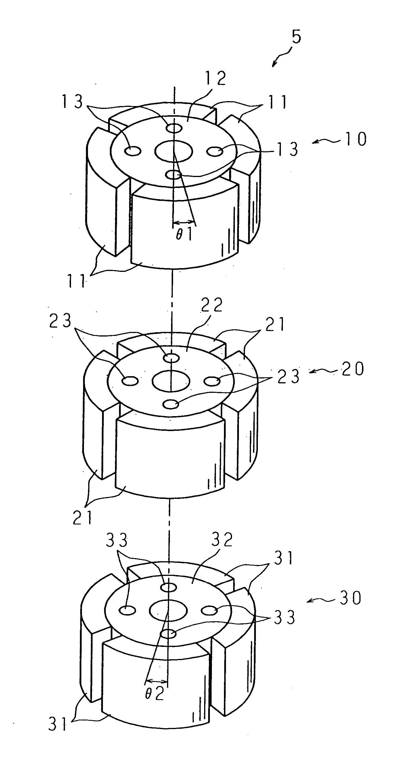
FIG. 10 is a perspective view showing the construction of a rotor of a brushless DC motor according to the first embodiment of the present invention. This rotor 5 is constructed by a rotor block 10 in the upper stage, a rotor block 20 in the middle stage, and a rotor block 30 in the lower stage. The rotor block 10 comprises an internal rotor core 12, and four permanent magnets 11 attached to the outer circumference of the rotor core 12 at equal intervals. The rotor block 20 comprises an internal rotor core 22, and four permanent magnets 21 attached to the outer circumference of the rotor core 22 at equal intervals. The rotor block 30 comprises an internal rotor core 32, and four permanent magnets 31 attached to the outer circumference of the rotor core 32 at equal intervals.

The rotor cores 12, 22 and 32 have the same size, and each of which comprises four coupling member insertion holes 13, 23, 33 for fixing the rotor blocks 10, 20 and 30 integrally with coupling...

second embodiment

(Second Embodiment)

FIGS. 14A, 14B and 14C show the construction of a rotor of a brushless DC motor according to the second embodiment of the present invention by a plan view (FIG. 14A) and cross sectional views (FIGS. 14B and 14C) in a direction perpendicular to the rotary shaft. This rotor is a permanent magnet-buried type rotor constructed by inserting permanent magnets into empty holes formed in a rotor core, and comprises a rotor core 17 and four sets of permanent magnets fitted at equal intervals into four empty holes 19 formed in the outer circumferential portion of the rotor core 17 at equal intervals along the outer circumference.

Each of the four sets of permanent magnets is composed of three permanent magnets 16, 26 and 36 located in the upper, middle and lower stages, the upper stage being one end in the direction of the rotary shaft. The permanent magnets 16, 26 and 36 have the same size. The rotor core 17 is formed by layering a number of thin electromagnetic steel pla...

third embodiment

(Third Embodiment)

As shown in FIG. 15, the third embodiment is implemented by applying the present invention to a brushless DC motor comprising a magnet-buried type rotor 5 having four magnetic poles. In other words, the rotor 5 of this brushless DC motor has magnet mounting holes 8 formed at four positions along the outer circumference, and permanent magnets 7 are mounted in the magnet mounting holes 8, respectively. The permanent magnets 7 are arranged adjacent to the outer circumference of the rotor 5. For this reason, it can be said that the opening angle of each permanent magnet 7 seen from a rotational center axis O is equal to the effective polar opening angle. The permanent magnets 7 are arranged so that adjacent permanent magnets 7 have mutually opposite polarities. A stator 1 comprises a yoke 2 as an outer circumferential portion, and twelve teeth 3 that are provided at equal intervals and protrude from the yoke 2 toward the center. Adjacent teeth 3 form a slot 4 together...


PUM

PropertyMeasurementUnit
electrical angleaaaaaaaaaa
lengthaaaaaaaaaa
angleaaaaaaaaaa

Abstract

A brushless DC motor including a stator having plural slots; and a rotor which has plural permanent magnets and is divided into three rotor blocks in a rotation axis direction, the three rotor blocks being layered so that the arrangement angles of the rotor blocks differ from each other by an amount of a mechanical angle in a rotary direction that is equivalent to one third of a pulsation period of cogging torque generated by the rotor and stator. A brushless DC motor including a rotor having plural magnetic poles provided at an equal pitch in a circumferential direction by mounting permanent magnets in magnet mounting holes; and a stator having plural slots arranged at an equal pitch in a circumferential direction. The magnetic poles of the rotor include magnetic poles whose magnet deviation angle formed by the central line of an effective polar opening angle and the central line of the magnet mounting hole is the first angle; and magnetic poles whose magnet deviation angle is the second angle different from the first angle.

Description

BACKGROUND OF THE INVENTION The present invention relates to a brushless DC motor comprising a rotor having permanent magnets, and more particularly relates to a brushless DC motor capable of reducing cogging torque and a manufacturing method of the same. A brushless DC motor is a motor that comprises a rotor having permanent magnets and rotates the rotor by controlling an electric commutator circuit for generating a rotational magnetic field in a stator, based on a detection signal representing the rotational position of the rotor. Since the brushless DC motor does not generate mechanical and electrical noises and has high rotary performance and a long life, it is mainly used in the cylinder of a VTR, the capstan of a cassette tape deck, a flexible disk driver, a CD player, etc. In recent years, the brushless DC motor is used in the drive motor of a power steering apparatus for vehicle. In the brushless DC motor, torque pulsation, i.e., cogging torque, is unavoidably produced be...

Claims


Application Information

Patent Timeline
Patent Type & Authority Applications(United States)
IPC IPC(8): H02K1/27H02K29/03
CPCH02K1/278Y10T29/49009H02K2201/06H02K29/03
Inventor INAYAMA, HIROHIDEJONOKUCHI, HIDEKIMORI, SADAAKIISHIHARA, ATSUSHITAKAHASHI, TOMOFUMIKITABAYASHI, MINORUHORIE, TETSUO
Owner KOYO SEIKO CO LTD
Why Eureka
Try Eureka