
Automatic Lockset Tamper Detection Device and Method

a detection device and lockset technology, applied in the direction of alarm locks, mechanical actuation of burglar alarms, instruments, etc., can solve the problems of increased time and care required to disable, false alarms and missed alarms, and unwanted attention, and achieve the effect of significantly increasing the capacitance between the lockset and the vertical wir

Active Publication Date: 2005-02-10
MAJOR MONITORS
View PDF9 Cites 16 Cited by
  • Summary
  • Abstract
  • Description
  • Claims
  • Application Information

AI Technical Summary

Benefits of technology

[0006] The two contacts within the bolt recess operate cooperatively to signal whether the bolt is in its extended and locked position or in its retracted and open position. The active, or energized, of the two contacts also serves to convey a low-level RF signal to the entire lockset including all externally accessible mounting and operational features. When a person standing by the door touches any part of the energized lockset, the capacitance measured between the lockset and the vertical wire is significantly increased.

Problems solved by technology

Home security systems are notoriously subject to both false alarms and missed alarms.
The principal failing of these systems is in the extra time and care required to disable security systems before entry and to enable them upon leaving.
Further, forced entry is usually noisy and may result in unwanted attention.

Method used


Image

  • Automatic Lockset Tamper Detection Device and Method
  • Automatic Lockset Tamper Detection Device and Method
  • Automatic Lockset Tamper Detection Device and Method

Examples


Embodiment Construction

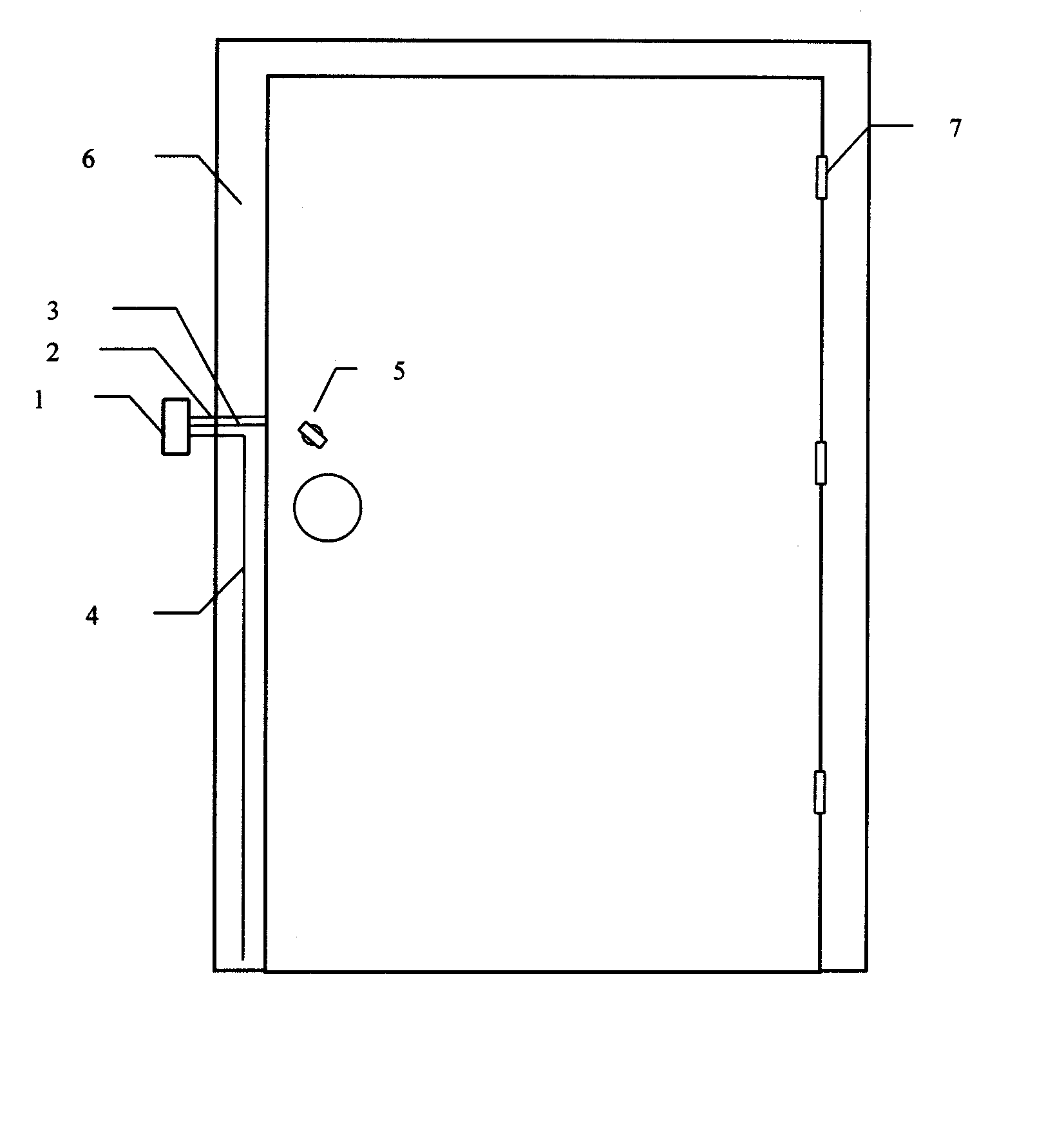
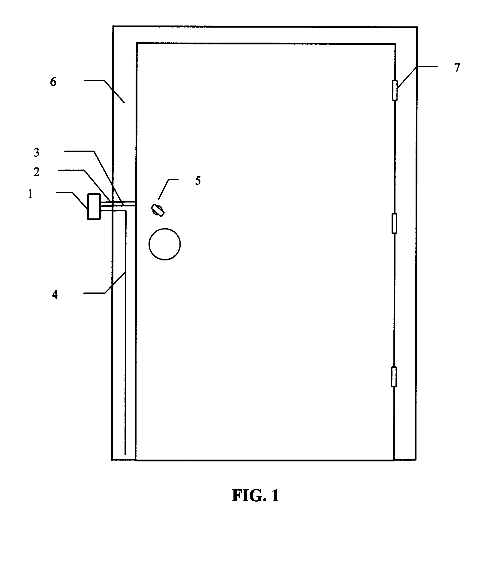
[0012] Referring now to FIG. 1, there is shown a door with lockset. The door is fitted into door frame 6 to which it is secured by hinges 7. To lock or unlock the door from the inside, bolt actuator 5 is rotated in one direction so as to extend the bolt and thereby lock the door, or in the opposite direction to retract the bolt and unlock the door. Generally this operation is accomplished by a key on the outside or a rotatable knob on the inside. Adapted to the door and frame are three conductors, 2, 3, and 4, shown as they are positioned within a ribbon cable and against the door frame.

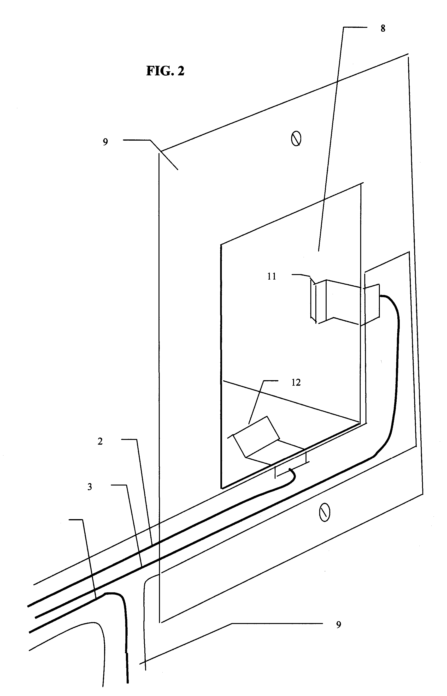
[0013]FIG. 2 shows bolt receptacle 8, latch plate 9, and two leaf-spring contacts 11 and 12. The leaf-spring contacts are secured within the bolt receptacle so as to ensure that they are wiped by the metal bolt as it extends or retracts. The material, position, and shape of these contacts ensures reliable electrical contact with the bolt and provides sufficient deflection so as to not interfere with...


PUM


Abstract

A device for detecting tampering with standard mechanical lock-sets has a pair of electrical contacts placed within the recess that receives lock's bolt. These contacts provide an electrical connection to the bolt and hence the entire lockset when the bolt is in its extended or locked position. The two contacts are connected to individual conductors in a cable that also has a third conductor positioned to run vertically along the door frame below the bolt receptacle. All three conductors merge in a short horizontal run of cable to a control box secured to an interior door frame or wall. The control box sends a low-level radio frequency (RF) signal to the first contact that in turn energizes the entire lockset when the bolt is in its extended position. The second contact returns RF energy to the control box to signal that the bolt is in its extended or locked position. The third conductor is connected to circuit common and used to measure capacitance between energized conductors and circuit common. Measured changes in capacitance, in conjunction with control box logic, serve to automatically enable tamper detection when the lockset is in its locked position. Further, to automatically signal an alarm when the locked lockset is tampered with and to automatically disable tamper detection when the lockset is in its unlocked position. The doors and other portals of entry or exit secured with this lockset tampering detection device serve to define one or more protected areas whose status may then be signaled through conventional multi-zone security systems.

Description

CROSS REFERENCE TO RELATED APPLICATIONS [0001] This application is a continuation of my Provisional Patent Application No. 60 / 319,451 filed Aug. 6, 2002BACKGROUND OF INVENTION [0002] Home security systems are notoriously subject to both false alarms and missed alarms. Over 90% of home security alarms are reported to be false alarms. Missed alarms, from failure to turn the security system on, are estimated to occur 30% to 50% of the time. The principal failing of these systems is in the extra time and care required to disable security systems before entry and to enable them upon leaving. [0003] Law provides more severe penalties for “Breaking and Entering” than for apparently non-forced entry. Further, forced entry is usually noisy and may result in unwanted attention. Would-be intruders can therefore be expected to first try passkeys, lock picks or like tests of lock integrity before generating evidence of forcible entry. [0004] The acts of locking a door behind on leaving and unloc...

Claims


Application Information

Patent Timeline
Patent Type & Authority Applications(United States)
IPC IPC(8): E05B45/06E05B45/08
CPCE05B45/083E05B45/06
Inventor MEIJER, ROBERT S.
Owner MAJOR MONITORS
Learn More