
Capacitance measuring apparatus and capacitance measuring method

a capacitance measurement and capacitance measurement technology, applied in the field of capacitance measuring apparatus and capacitance measuring method, can solve the problems of inability to accurately measure the amount of inability to optimize and inability to accurately measure the change in the charging charge of the device under test. achieve the effect of improving the dynamic range, improving the s/n (signal-to-noise ratio), and optimizing the measurement range of the ammeter

Active Publication Date: 2010-10-12
KEYSIGHT TECH
View PDF7 Cites 2 Cited by
  • Summary
  • Abstract
  • Description
  • Claims
  • Application Information

AI Technical Summary

Benefits of technology

The present invention provides a capacitance measuring apparatus and method that can accurately measure capacitance even in devices with large leakage currents. The apparatus includes a voltage source, a current source, and an ammeter to measure the leakage current and the charging current. The current source absorbs the current through the resistance component of the device under test, while the voltage source applies voltage fluctuations. The ammeter measures the leakage current before and after voltage fluctuations and the charging current resulting from voltage fluctuations. By optimizing the measurement range of the ammeter and improving the dynamic range and signal-to-noise ratio, the apparatus can accurately measure capacitance. The use of a floating current source ensures stable current conditions and prevents noise from affecting the output current. Overall, the invention provides a reliable and precise method for measuring capacitance.

Problems solved by technology

However, there is a problem with the micro / nano-level processing of semiconductors in that in the case of a capacitance measurement at low frequency in particular, a large leakage current attributed to the resistance component of the device under test flows into the ammeter for measuring the charging current flowing to the device under test, and this leads to errors in the capacitance measurement. FIG. 10 shows an example of the effect of this leakage current.
If there is no leakage current, the only current flowing into the ammeter will be charging current that is flowing through the device under test, but when leakage current is generated, in addition to the charging current flowing through the device under test, leakage current flows into the ammeter.
As a result, it is not possible to correctly measure the amount of change in the charging charge of the device under test.
Nevertheless, by means of the above-mentioned conventional method for measuring capacitance there is a problem in that when the leakage current becomes much larger than the charging current, the leakage current accounts for more of the current flowing through the ammeter than does the charging current, the charging current becomes a small part of the ammeter measuring range, and there is a reduction in the timing range and the S / N (signal-to-noise ratio).

Method used


Image

  • Capacitance measuring apparatus and capacitance measuring method
  • Capacitance measuring apparatus and capacitance measuring method
  • Capacitance measuring apparatus and capacitance measuring method

Examples


Embodiment Construction

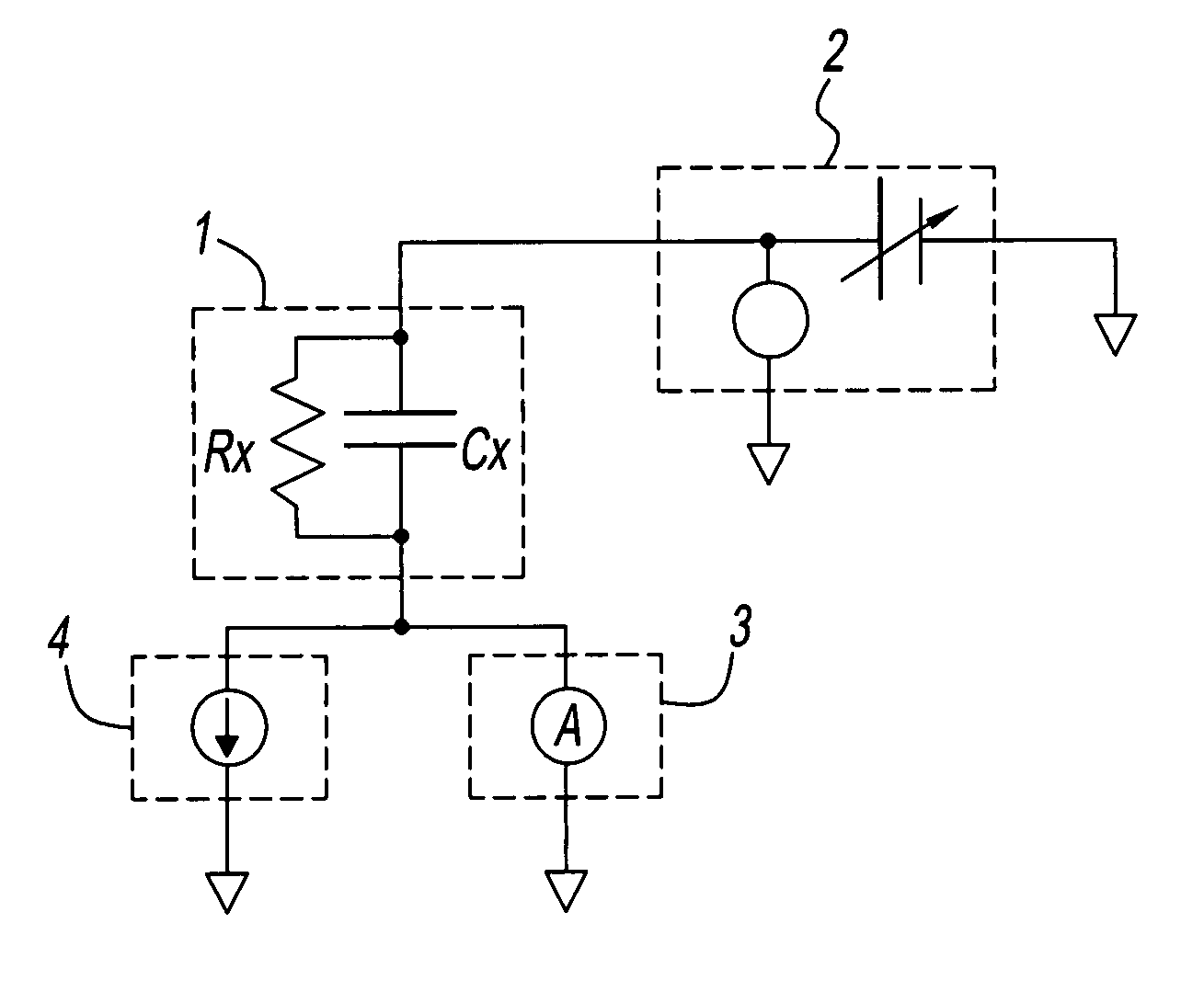
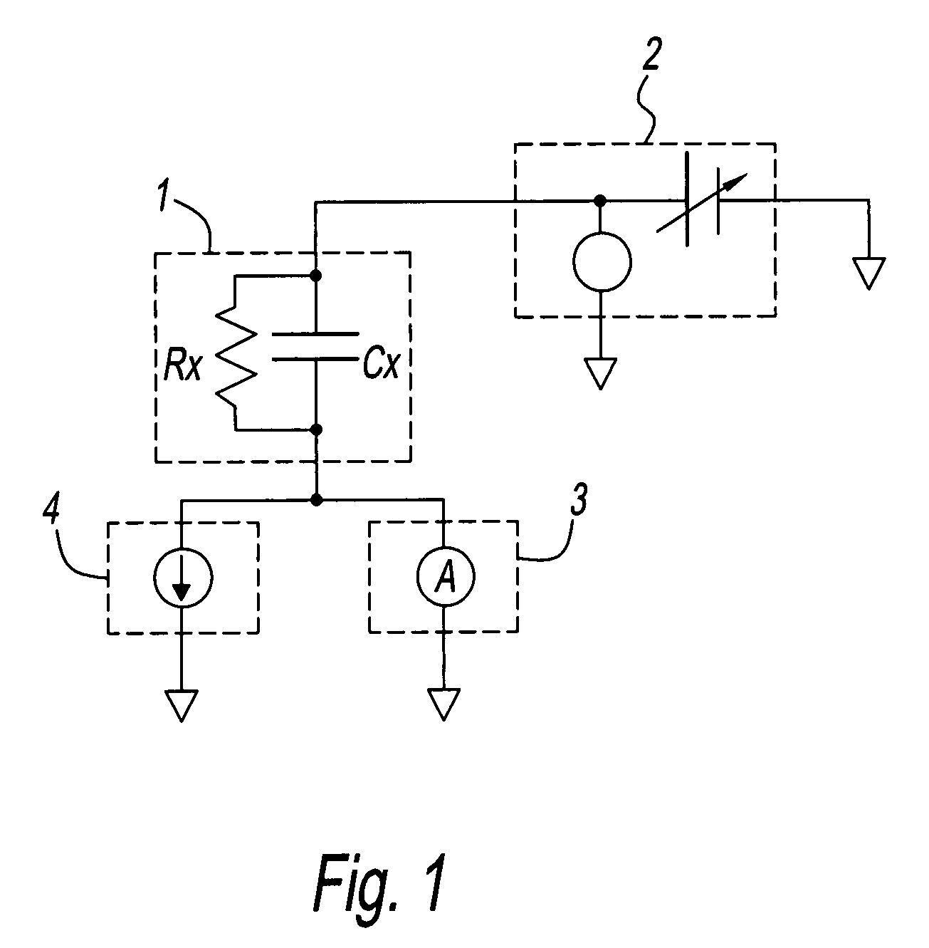
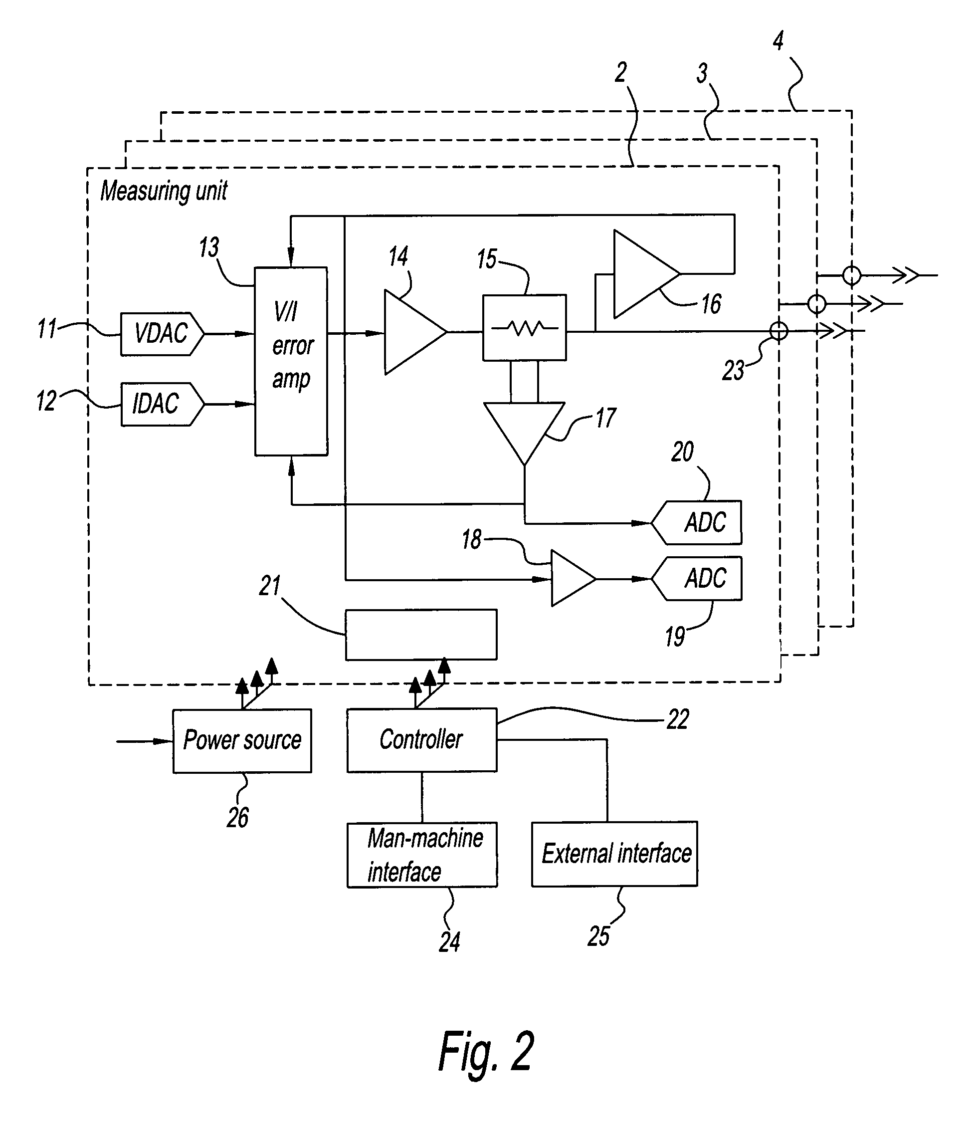
[0044]Embodiments of the present invention will now be described while referring to the drawings. FIG. 1 is a drawing showing the connection between the capacitance measuring apparatus of an embodiment of the present invention and a device under test. As is shown in the same figure, this capacitance measuring apparatus comprises a first measuring unit 2 that operates as a step voltage source for applying step voltage such that voltage fluctuation is applied to device under test 1; a second measuring unit 3 that operates as an ammeter for measuring the leakage current that flows through the device under test 1 before and after voltage fluctuation and charging current that flows through device under test 1 when voltage fluctuates; and a third measuring unit 4 that operates as a current source for absorbing current that flows through resistance component Rx of device under test 1. Cx is the capacitance component of device under test 1, and Rx is the resistance component of device under...


PUM


Abstract

A capacitance measuring apparatus which comprises: a voltage source for applying voltage fluctuation to a device under test; a current source for absorbing the current flowing through the resistance component of the device under test; and an ammeter for measuring the leakage current flowing through the device under test before and after voltage fluctuation and the charging current flowing through the device under test as a result of voltage fluctuation.

Description

BACKGROUND[0001]1. Field of the Disclosure[0002]The present invention relates to a capacitance measuring apparatus and capacitance measuring method that are used for quasi-static capacitance measurement of a capacitance element in the development of semiconductor devices and semiconductor processes.[0003]2. Discussion of the Background Art[0004]The capacitance of a device under test (DUT) is measured as part of the evaluation that is performed in the development of semiconductor devices and semiconductor processes. The capacitance measurement of a device under test generally is a capacitance measurement at high frequency or a capacitance measurement at low frequency (quasi-static capacitance measurement). As a result of semiconductor processes being conducted on micro / nano levels in recent years, the measured capacitance at a low frequency has become smaller, and there is a need for technology with which high-precision measurement is possible.[0005]The step voltage method is a means...

Claims


Application Information

Patent Timeline
Patent Type & Authority Patents(United States)
IPC IPC(8): G01R27/26G06G7/12
CPCG01R27/2605
Inventor TANIDA, SHINICHINADA, HIROSHIIKAWA, TOMOE
Owner KEYSIGHT TECH
Learn More