
Portable air moving device

a high-speed fan and air-moving technology, which is applied in the direction of rotors, marine propulsion, vessel construction, etc., can solve the problems of large axial fan blades, large air movement volume, and large air movement, and achieve efficient impingement of the skin of the user, rapid moisture evaporation, and maximum moisture evaporation

Active Publication Date: 2005-02-10
LASKO OPERATION HLDG LLC
View PDF24 Cites 147 Cited by
  • Summary
  • Abstract
  • Description
  • Claims
  • Application Information

AI Technical Summary

Benefits of technology

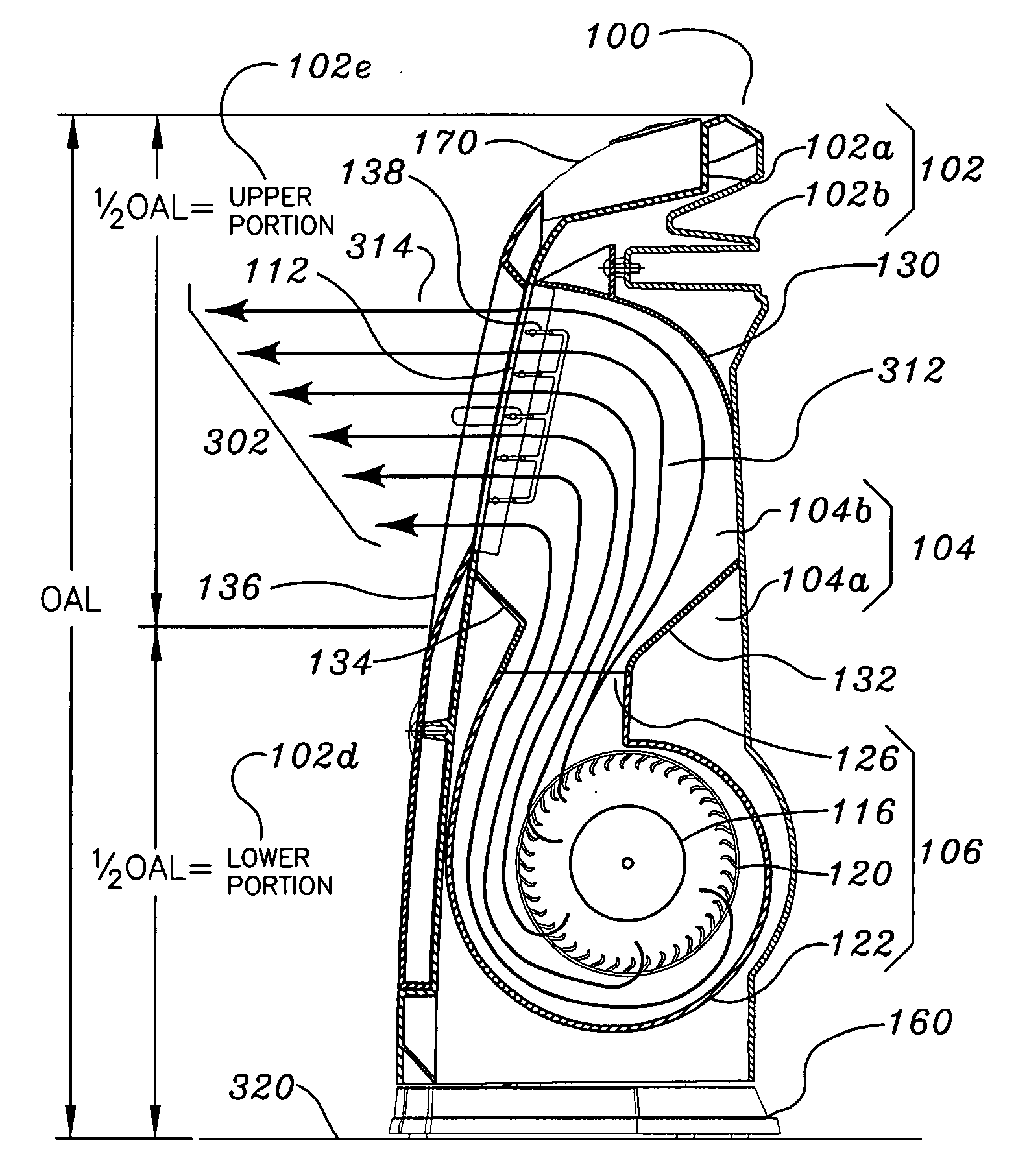
[0005] In light of the shortcomings of the prior art, the present invention is directed to a high velocity air movement device that produces an air steam of sufficient velocity to maximize the evaporation of moisture (sweat) from the skin of the user. This can be achieved in that the velocity of the air stream allows it to efficiently impinge the surface (skin) of the user and rapidly evaporate the moisture. One manner to enhance this effect is to raise the elevation of the high velocity air stream, thus allowing the air stream to impinge on the user's upper body. The upper body is more exposed and therefore will experience the effects of the cooling more quickly.
[0006] In another embodiment of the invention, a high velocity air moving device allows a user to have the ability to direct and focus the air stream to a desired location. This helps to alleviate or lessen the disturbance of other objects in the area as mentioned, while allowing the user to experience the cooling advantages of a high velocity air moving device

Problems solved by technology

These types of devices not only produce a high velocity air stream but also produce a large volume of air movement.
A disadvantage of this device is that the axial fan blade is large and requires even larger protective grills.
Another disadvantage of this device is that the large volumes of air combined with the high velocity of the air stream produce a large thrust.
The thrust stability problem can be exacerbated if the device is elevated above its support surface.
The large components (blades and protective grills) of axial fans along with the increased thrust and corresponding stability problems do not allow these types of devices to be easily transportable (portable) or to have space saving characteristics.
Another disadvantage of these conventional devices is that the high volume of air that is moved by the device may not be desirable.
The high volume of air may cause objects, (such as papers for example) to be dislodged from their intended place.
Further, the large volume of air increases the possibility that dust, pollen, dander, etc. will be disturbed and induced to become airborne.
The airborne dust and debris can be detrimental to, for example, respiratory conditions.

Method used


Image

  • Portable air moving device
  • Portable air moving device
  • Portable air moving device

Examples


Embodiment Construction

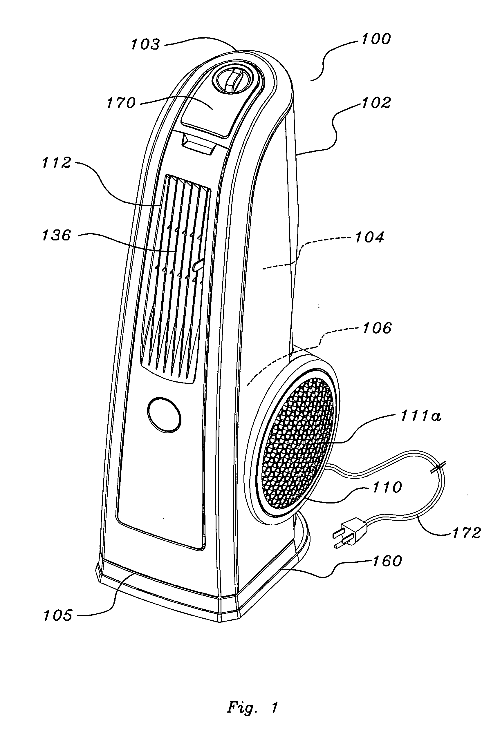
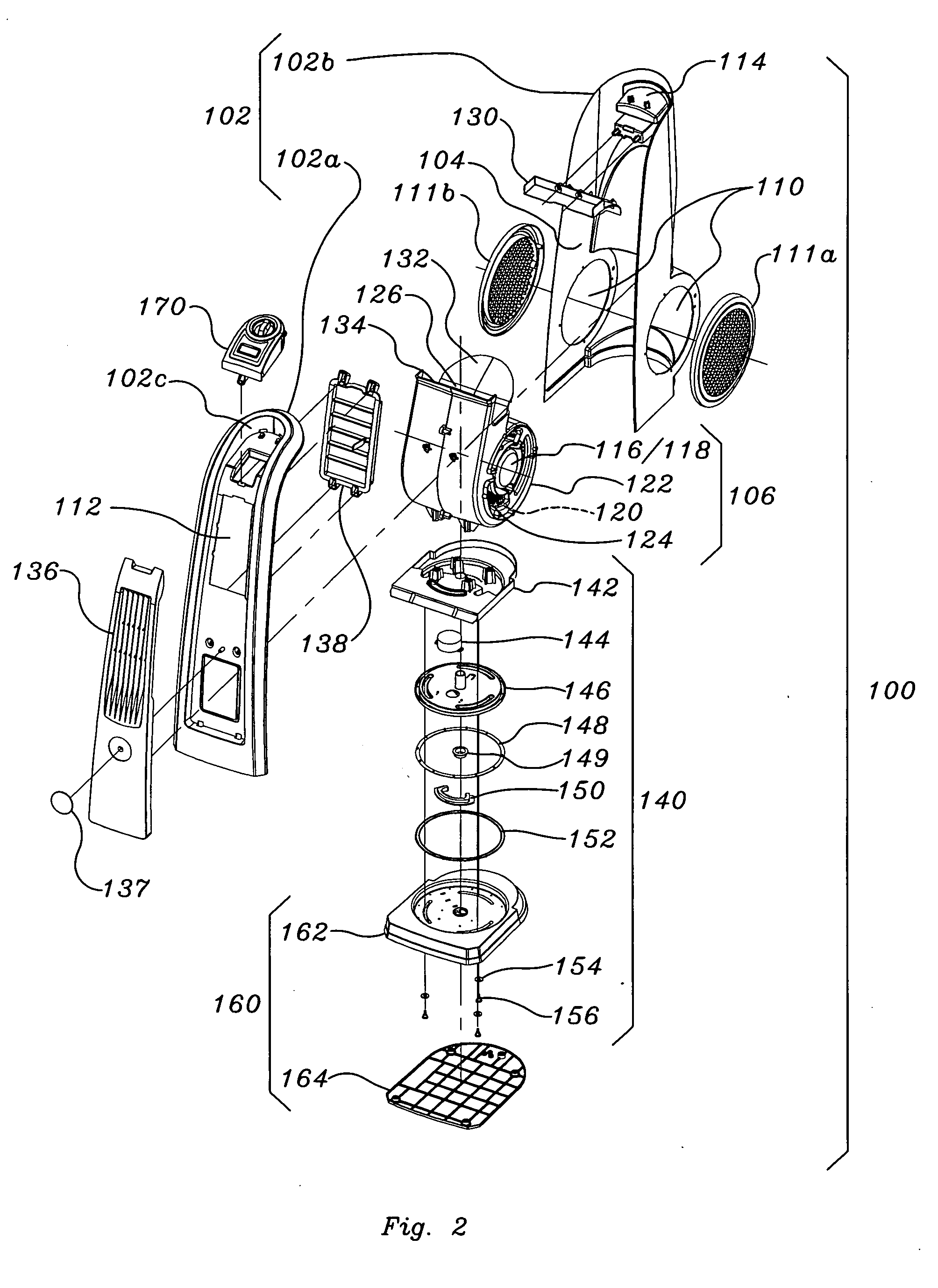
[0027] The following description is of a portable air moving device that generates a focused stream of high velocity air that is easily directed by the user to a desired location. The device also has a vertical aspect ratio relative to a support surface, which allows the generated air stream to affect the user's upper body more readily. The device also has space saving characteristics. In addition, the high velocity air moving device is preferably portable and can be easily moved by the user to a desired location. The air blower assembly of the device uses an air generator having an impeller and motor design that is relatively inexpensive to manufacture. In other embodiments, the high velocity air moving device provides various combinations of the above characteristics at a desirable retail cost for the consumer.

[0028]FIG. 1 shows an exemplary perspective view of portable air moving device 100. Portable air moving device 100 includes housing 102 having at least one side wall extend...


PUM


Abstract

A stable portable air moving device capable of generating an air stream elevated above a support surface allowing the air stream to be directed as desired by the user is provided. The device includes an air blower assembly located within an elongate housing generating an exhaust air stream that exits the elongate housing at an elevation above the air blower assembly.

Description

CROSS-REFERENCE APPLICATIONS [0001] This application is a Continuation-in-Part of application Ser. No. 10 / 347,079, filed Jan. 17, 2003, which is a Continuation-in-Part of application Ser. No. 10 / 322,169, filed Dec. 18, 2002.FIELD OF THE INVENTION [0002] This invention relates generally to fans. More specifically, the present invention relates to portable high velocity fans. BACKGROUND OF THE INVENTION [0003] High velocity air moving devices have been utilized for many years. One example of a conventional device includes an axial fan blade type impeller and a motor. These types of devices not only produce a high velocity air stream but also produce a large volume of air movement. A disadvantage of this device is that the axial fan blade is large and requires even larger protective grills. Another disadvantage of this device is that the large volumes of air combined with the high velocity of the air stream produce a large thrust. The thrust must be counteracted by utilizing a large ba...

Claims


Application Information

Patent Timeline
IPC IPC(8): F24H3/04
CPCF24H3/0417
Inventor LASKO, WILLIAM E.ORR, PAUL W.
Owner LASKO OPERATION HLDG LLC
Learn More