Fluid heater

A heater and fluid technology, used in fluid heaters, water heaters, lighting and heating equipment, etc., can solve the problems of fossil fuel air pollution, low thermal efficiency of fossil fuels, and few types of heater specifications to maximize thermal efficiency , The effect of minimizing air pollution and environmental pollution

Inactive Publication Date: 2009-03-04
穆斯塔法耶夫·拉斐尔 +1
View PDF0 Cites 1 Cited by
  • Summary
  • Abstract
  • Description
  • Claims
  • Application Information

AI Technical Summary

Problems solved by technology

[0006] Second, it is well known that fossil fuels produce large amounts of air pollution due to their incomplete combustion due to their low thermal efficiency
[0008] Fourth, heaters with various specifications of thermal efficiency suitable for the place where the heater is installed and the size of the building are required, but currently there are few types of specifications of heaters, which leads to low thermal efficiency

Method used


Image

  • Fluid heater
  • Fluid heater
  • Fluid heater

Examples


Embodiment Construction

[0032] Hereinafter, preferred embodiments of the present invention will be described in detail with reference to the accompanying drawings.

[0033] A fluid heater according to an embodiment of the present invention will be explained below with reference to the drawings.

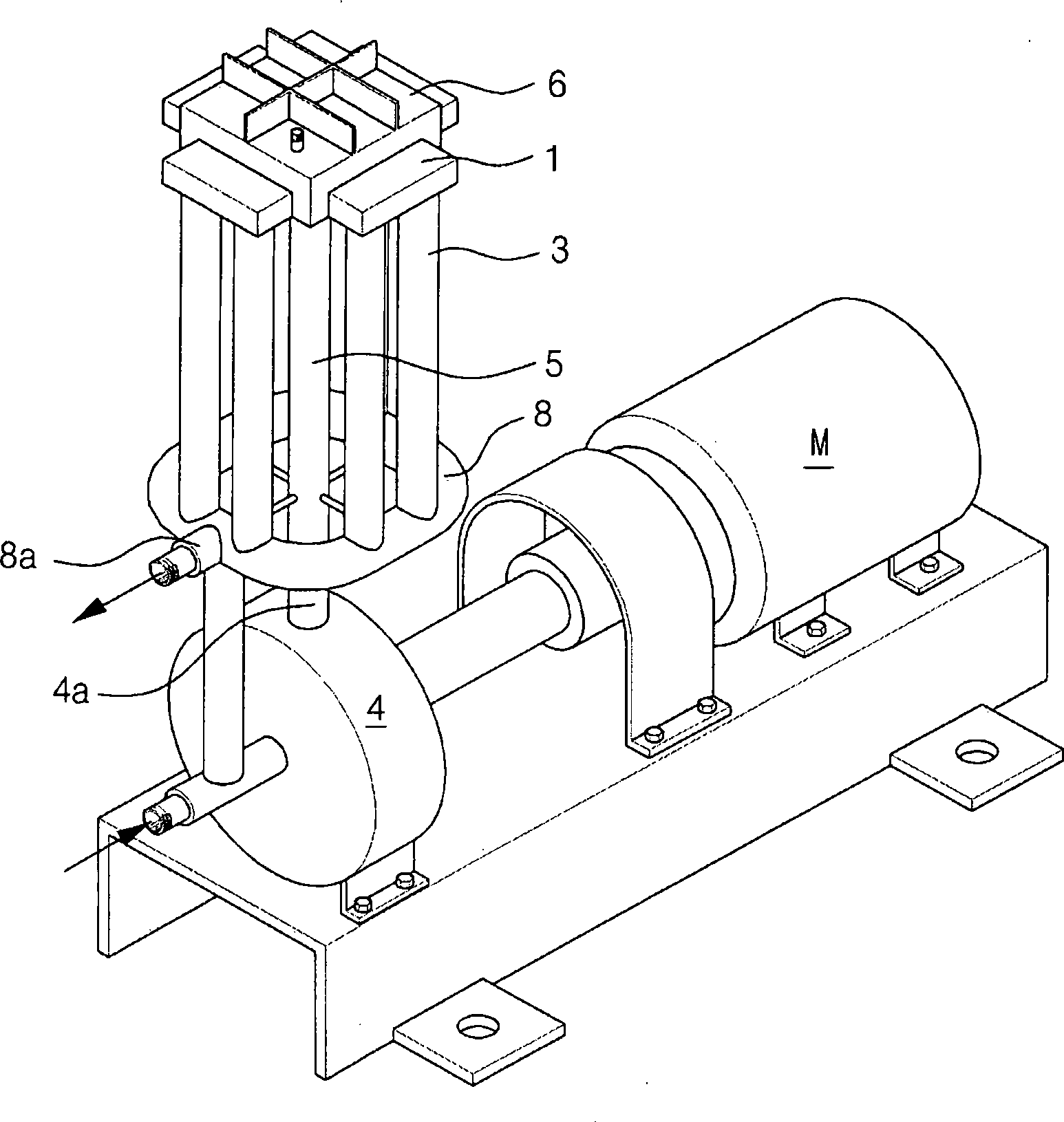
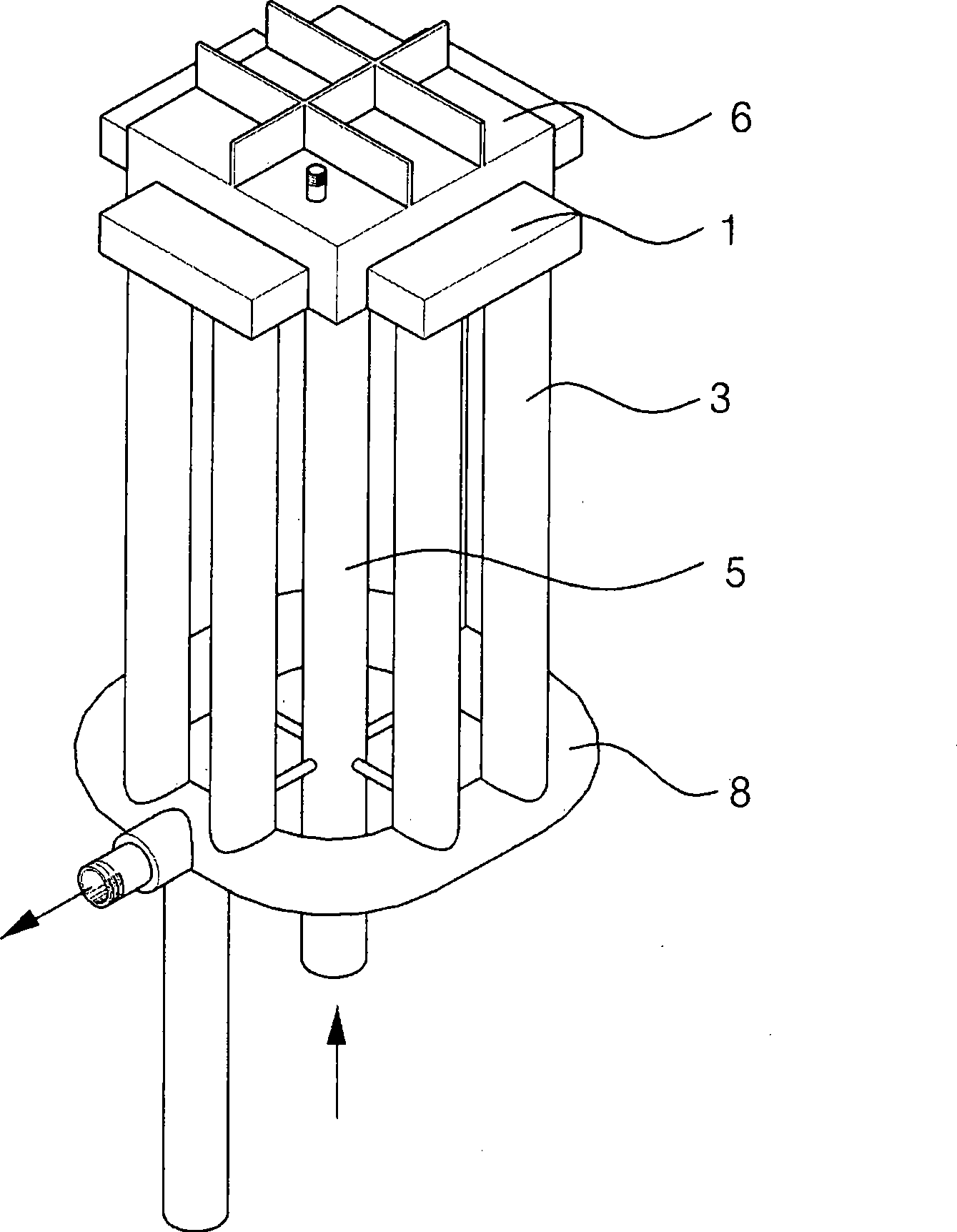
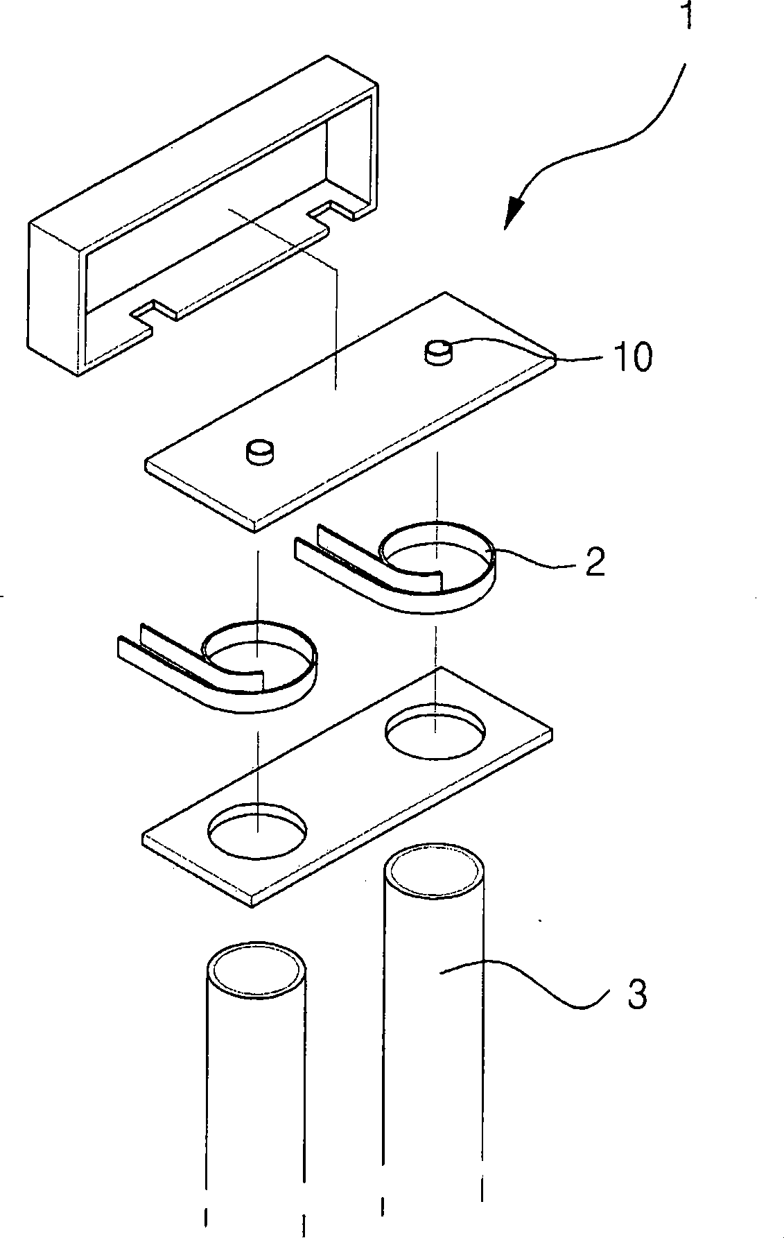
[0034] figure 1 is a perspective view of a fluid heater according to an embodiment of the present invention, figure 2 is a perspective view of a fluid heater connected to a pumping device according to an embodiment of the invention, image 3 is an exploded perspective view of a fluid flow acceleration component of a fluid heater according to an embodiment of the present invention, Figure 4 is a cross-sectional view illustrating the attenuator of the fluid heater, and Figure 5 is a cross-sectional view illustrating fluid flow in a fluid heater according to one embodiment of the present invention.

[0035] As shown in the drawings, the fluid heater includes: the generation tube 5 that moves the fluid up...


PUM


Abstract

The invention discloses a fluid heater that can be used as a heater in a residence or an industrial facility or that can be used to heat water in fishery, agricultural, and transportation industries. In particular, a fluid heater heats a fluid using a multi-channel structure of the flow of fluid passing through a branching system, instead of using additional fossil fuels. The generation of vibration and noise while heating the fluid is suppressed.

Description

technical field [0001] The present invention relates to a fluid heater which can be used as a heater in dwellings and industrial establishments, which can also be used for heating water in fishing, agriculture and transport, in particular the invention relates to a fluid heater , the fluid heater uses the principle of fluid flow through the multi-channel structure of the branch system instead of using auxiliary fossil fuels to heat the fluid, while suppressing the generation of vibration and noise during heating. Background technique [0002] A common example of a device employing heated water is a boiler, which can be used for various purposes. [0003] A boiler is a device that transfers combustion heat to water to generate steam by burning fossil fuels such as oil and coal. [0004] However, the boiler has the following problems. [0005] First, it is well known that fossil fuels lie underground in limited areas of the world, and only a limited number of countries posse...

Claims


Application Information

Patent Timeline
Patent Type & Authority Applications(China)
IPC IPC(8): F24J3/00
CPCF24H1/10F24J3/003F24V40/00Y02P80/10F24D2200/30F24H1/14F24H1/41F24H9/1809
Inventor 穆斯塔法耶夫·拉斐尔
Owner 穆斯塔法耶夫·拉斐尔
Why Eureka
Try Eureka