Method and apparatus for detecting a burner flame of a gas appliance

a technology for detecting the flame of the burner and the burner, which is applied in the direction of combustion process, combustion regulation, fuel supply regulation, etc., can solve the problems of reducing reliability, requiring electric power for operation, and adding complexity and expense to the gas appliance, so as to achieve simple, economical and reliable results

Inactive Publication Date: 2005-02-10
THETFORD CORP
View PDF10 Cites 3 Cited by
  • Summary
  • Abstract
  • Description
  • Claims
  • Application Information

AI Technical Summary

Benefits of technology

[0009] The present invention is directed to a method and apparatus for detecting a burner flame of a gas appliance. More particularly, the present invention is directed to a simple, economical and reliable apparatus for detecting a burner flame of a gas appliance and a related method. In one particular application, the apparatus for detecting the presence of a burner flame of a gas appliance includes a detection element for optically detecting the burner flame. The detection element is positioned adjacent to a location of the burner flame. The apparatus additionally includes a display element positioned remotely from the detection element. The display element is operative in a first mode to indicate the presence of a burner flame and a second mode to indicate the absence of a burner flame. The apparatus further includes a transmission element connecting the detection element and the display element. The transmission element causes the display element to operate in the first mode when the detection element optically detects the burner flame.

Problems solved by technology

Unfortunately, the required electronics for electronic flame monitors add complexity and expense to the gas appliance while decreasing reliability and requiring electric power for operation.
Such access holes significantly limit the vantage points from which the presence of the burner flame may be confirmed.
Accordingly, access to the burner flame is often inconvenient, impractical or even impossible.
While many prepared camp sites in parks and commercial campgrounds provide for electrical outlets, many do not.
In the case of an absorption refrigerator, a loss of flame results in a corresponding loss of refrigeration and a potential loss of the refrigerator contents.
Otherwise, the occupants may be unable to sleep or may loose their night vision upon waking.
The latter is disturbing because part of the enjoyment of camping involves appreciation of the brilliant night skies at remote camping sites.
Upon waking and loosing night vision due to uncontrolled light sources, an occupant desiring to access these permanent facilities may potentially stumble upon exiting the vehicle.
Thus, uncontrolled light sources may be inconvenient, or worst yet, hazardous for the occupants.
Since the prior art flame detectors function to maximize emitted light, they pose a potential hazard to the users of certain gas appliances, including but not limited to absorption refrigerators.
Inspection through an access hole is often impractical or unconventional.

Method used


Image

  • Method and apparatus for detecting a burner flame of a gas appliance
  • Method and apparatus for detecting a burner flame of a gas appliance
  • Method and apparatus for detecting a burner flame of a gas appliance

Examples


Embodiment Construction

[0020] The following description of the embodiments of the invention is merely exemplary in nature and is in no way intended to limit the invention, its application, or uses.

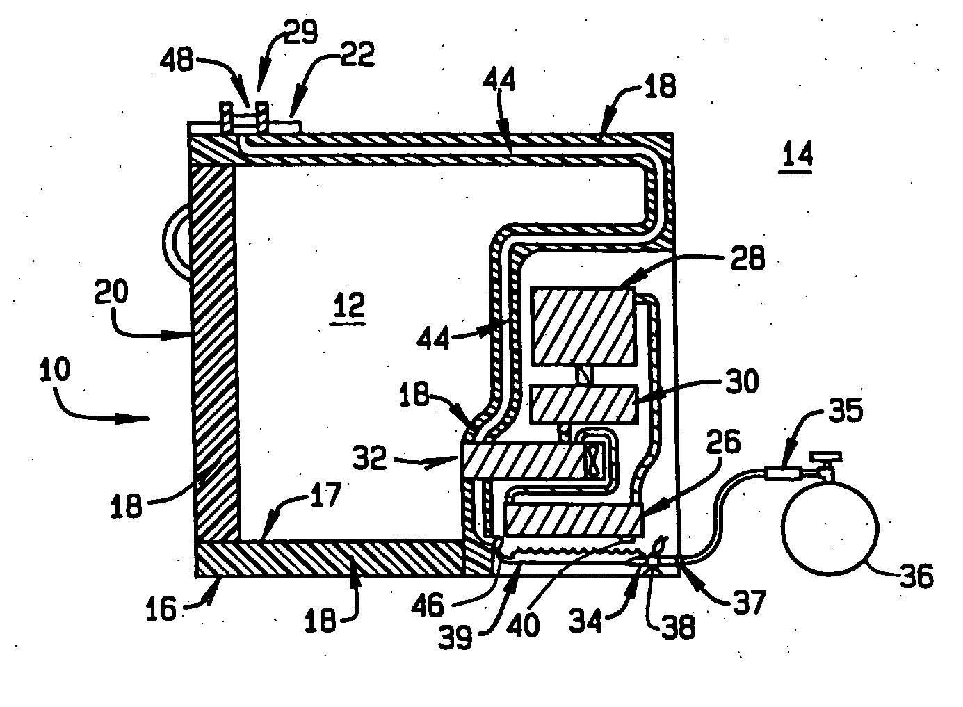
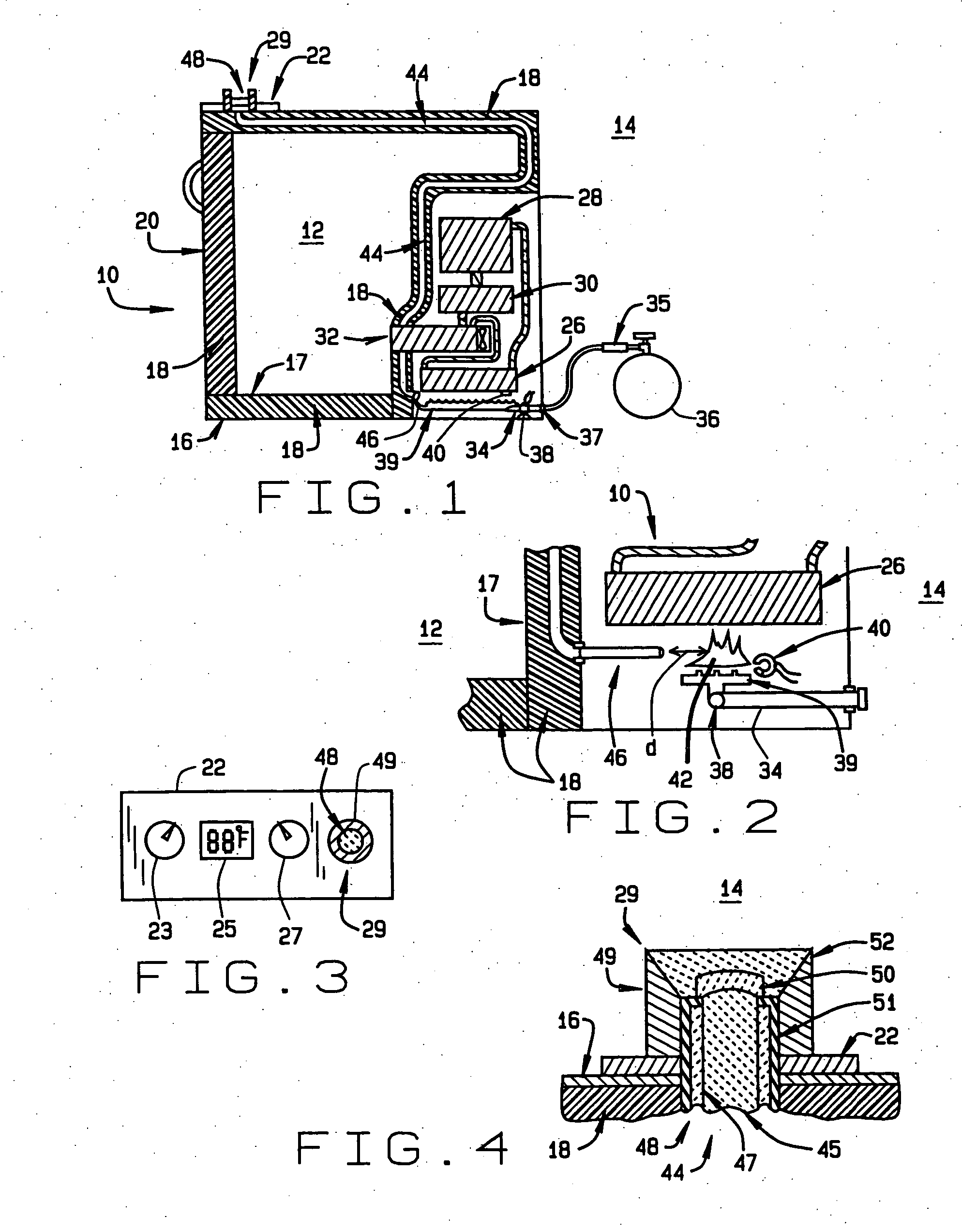
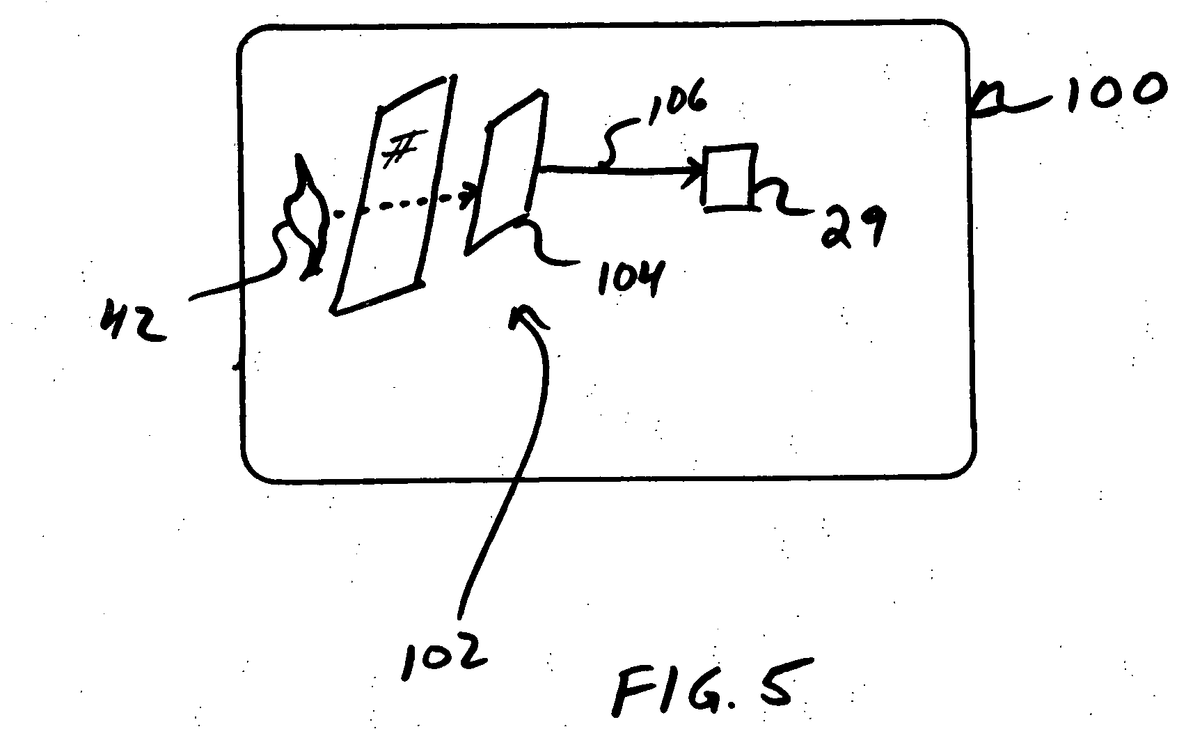
[0021] With initial reference to FIG. 1, an apparatus for detecting a burner flame of a gas appliance constructed in accordance with the teachings of a first embodiment of the present invention is illustrated and generally identified at reference character 8. The apparatus 8 is operatively associated with a gas appliance in the form of an absorption refrigerator 10. It will become apparent below to those skilled in the art that the teachings of the present invention have application beyond use with an absorption refrigerator 10. In this regard, it will be understood that the description of the present invention insofar as it is specifically directed to an absorption refrigerator is exemplary in nature.

[0022] Prior to addressing the specific teachings of the present invention, a brief understanding of the exemp...


PUM


Abstract

An apparatus for detecting the presence of a burner flame of a gas appliance includes a detection element for optically detecting the burner flame. The detection element is positioned adjacent to a location of the burner flame. The apparatus additionally includes a display element positioned remotely from the detection element. The display element is operative in a first mode to indicate the presence of a burner flame and a second mode to indicate the absence of a burner flame. The apparatus further includes a transmission element connecting the detection element and the display element. The transmission element causes the display element to operate in the first mode when the detection element optically detects the burner flame.

Description

CROSS REFERENCE TO RELATED APPLICATION [0001] This application claims priority to U.S. Provisional Patent Application No. 60 / 471,009 filed May 16, 2003 which is hereby expressly incorporated by reference herein in its entirety.FIELD OF THE INVENTION [0002] The present invention relates to a method and apparatus for detecting a burner flame of an appliance. More particularly, the present invention relates to a method and apparatus for detecting a flame of an appliance that incorporate a fiber optic element for transmission. More specifically, but without restriction to the particular embodiment and / or use which is shown and described for purposes of illustration, the present invention relates to a method and apparatus for detecting a flame of an appliance, such as an absorption refrigerator, that use a fiber optic element with light filters, light shields, and cable sheathing with indeces which can be designed and optimized for different appliances and applications. BACKGROUND OF THE...

Claims


Application Information

Patent Timeline
Patent Type & Authority Applications(United States)
IPC IPC(8): F23N5/24
CPCF23N5/242
Inventor EIL, LOUIS VANASHER, AMRAM
Owner THETFORD CORP
Why Eureka
Try Eureka