
Electric radiator type heating apparatus including a voltage converter

a technology of electric radiators and heating apparatuses, applied in lighting and heating apparatus, gaseous heating fuel, stoves or ranges, etc., can solve the problems of generating yield losses that are unacceptable, unable to meet the satisfaction of known heating appliances, and a very large limitation of the nature of electric power supply sources, so as to avoid overheating of voltage converters and optimize the energy efficiency of electrical appliances. , the effect of rapid preheating of other components

Inactive Publication Date: 2019-12-19
LANCEY ENERGY STORAGE
View PDF21 Cites 0 Cited by
  • Summary
  • Abstract
  • Description
  • Claims
  • Application Information

AI Technical Summary

Benefits of technology

The invention provides a simple and efficient heating appliance that can be easily used with direct electric power sources. It improves overall yields and uses a second flux to quickly preheat other components and optimize energy efficiency by avoiding calories produced by the voltage converter. These multiple functions work together to create a synergistic effect.

Problems solved by technology

Nonetheless, these known heating appliances do not yet give complete satisfaction.
Indeed, they confer a very great limitation as to the nature of the electric power supply source, excluding the possibilities of operation via an electric power source delivering a direct electric voltage such as a photovoltaic equipment, a fuel cell, a supercapacitor or an electrochemical cells-based battery, except for generating yield losses that are unacceptable.
It is recalled that the conversion of a direct voltage into an alternating voltage and the reverse conversion induce very substantial yield losses.
Moreover, in the current state of knowledge, electrical heating appliances cannot participate actively in the management of the electrical grid: the control and the storage capacity of the heating appliances are too limited (wired management, storage by thermal inertia) to respond quickly to the energy storage and supply needs.
Conventionally, the energy management system of a premises or a building using electrical heating appliances cannot participate in the integration of renewable energies on the electrical grid.
Indeed, the use of the inertia of the electrical heating appliances does not enable a sufficiently fine control to use the heating appliances as an intermittent storage system for renewable energies or to serve for consumption cut-off.

Method used


Image

  • Electric radiator type heating apparatus including a voltage converter
  • Electric radiator type heating apparatus including a voltage converter

Examples


Embodiment Construction

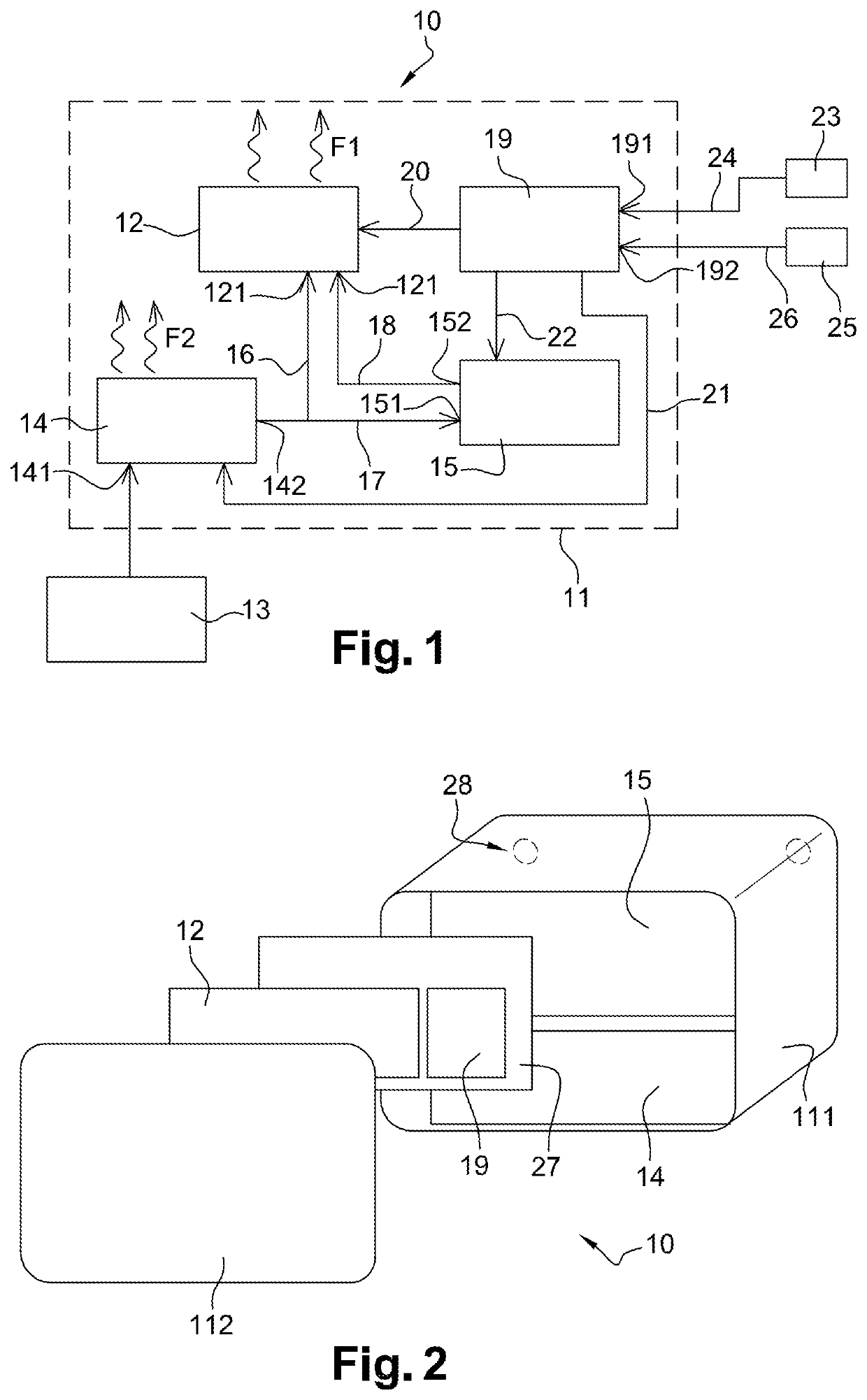
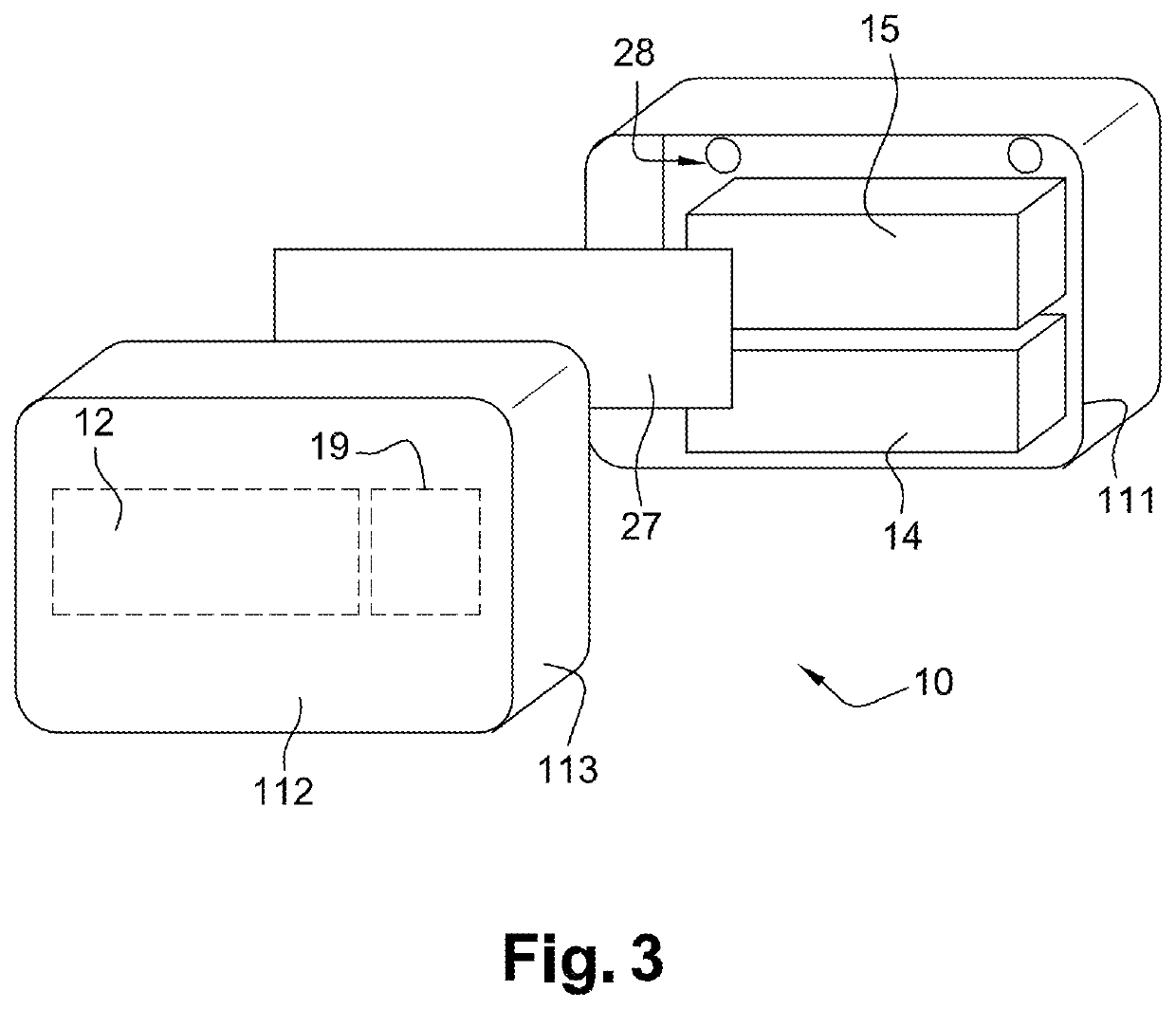
[0037]Referring to the appended FIGS. 1 to 3 as summarized hereinabove, the invention essentially concerns an electrical radiator type heating appliance 10, comprising a case 11 housing a heater member 12 producing a first flow of calories F1 when an input 121 of the heater member 12 is powered by a direct electric voltage.

[0038]The heater member 12 may in particular comprise at least one radiating body and / or at least one heating device by a heat transfer fluid.

[0039]The invention also concerns an electrical installation comprising an electric power supply source 13 and at least one such heating appliance 10. As will be understood from the explanations that follow, the electric power supply source 13 may be of the type delivering an alternating electric voltage, or even more advantageously, be of the type delivering a direct electric voltage.

[0040]The heating appliance 10 comprises a voltage converter 14 implanted in the case 11 and comprising an input 141 provided with connection ...


PUM


Abstract

An electrical radiator type heating appliance comprises a case housing a heater member producing a first flow of calories (F1) when an input of the heater member is powered by a direct electric voltage. The heating appliance also comprises a voltage converter implanted in the case and comprising an input provided with connection elements for connecting the voltage converter to an electric power supply source and an output delivering a direct electric voltage adapted to directly or indirectly power the input of the heater member.

Description

CROSS REFERENCE TO RELATED APPLICATIONS[0001]This application is a National Stage of PCT Application No. PCT / FR2017 / 053242 filed on Nov. 24, 2017, which claims priority to French Patent Application No. 16 / 61447 filed on Nov. 24, 2016, the contents each of which are incorporated herein by reference thereto.TECHNICAL FIELD[0002]The present invention concerns an electrical radiator type heating appliance, comprising a case housing a heater member producing a first flow of calories when an input of the heater member is powered by an electric voltage.[0003]The invention also concerns an electrical installation comprising an electric power supply source and at least one such heating appliance.BACKGROUND[0004]Conventionally, the electric power supply source to which the heating appliance is connected delivers an alternating electric voltage and all components of the heating appliance are adapted accordingly. Conventionally, this power supply source is constituted by the local electrical ne...

Claims


Application Information

Patent Timeline
IPC IPC(8): F24H9/20H05B1/02F24H3/00F24H9/02F24D18/00
CPCF24H9/02H05B1/0277F24H3/002F24H9/2071F24C7/062H05B1/0252F24H2240/01F24D2101/30F24D18/00F24D2101/40F24H15/414F24H15/258F24H15/37F24C3/002
Inventor MEYER, RAPHAËLMOREAU, GILLESROMATIER, ANTOINE
Owner LANCEY ENERGY STORAGE
Learn More