Handle for a catheter and corresonding catheter

a technology of corresonant catheters and catheter handles, which is applied in the field of catheter handling, can solve problems such as compromised catheter functions, and achieve the effect of improving the handling of catheters

Active Publication Date: 2020-04-16
BIOTRONIK AG
View PDF0 Cites 0 Cited by
  • Summary
  • Abstract
  • Description
  • Claims
  • Application Information

AI Technical Summary

Benefits of technology

[0035]A simple and economical and reliable method for operating an above-described catheter, for example for releasing a self-expanding stent, includes the steps that the release button is actuated and that the brake hose is then displaced together with the pull cable arranged therein in a longitudinal direction of the sleeve and relative to the sleeve and the inner shaft in a proximal direction. If the handle has a reel connected to the pull cable, the brake hose is displaced relative to the sleeve of the handle in a proximal direction by means of rotation of the reel mounted rotatably on the housing of the handle in order to wind up the pull cable and / or the brake hose. The pull cable is therefore retracted by rotation at the reel. The reel for this purpose for example has a fluting on an outer edge of a rotary wheel rigidly connected to the reel, which fluting facilitates a rotation of the reel. Alternatively or additionally, the reel is made of a soft material (for example a soft plastic), which also ensures greater friction between the reel and pull cable.

Problems solved by technology

Handles of known catheters often have the problem that as the pull cable is retracted it winds around the inner shaft of the catheter.
The function of the catheter is compromised as a result.

Method used


Image

  • Handle for a catheter and corresonding catheter
  • Handle for a catheter and corresonding catheter
  • Handle for a catheter and corresonding catheter

Examples


Embodiment Construction

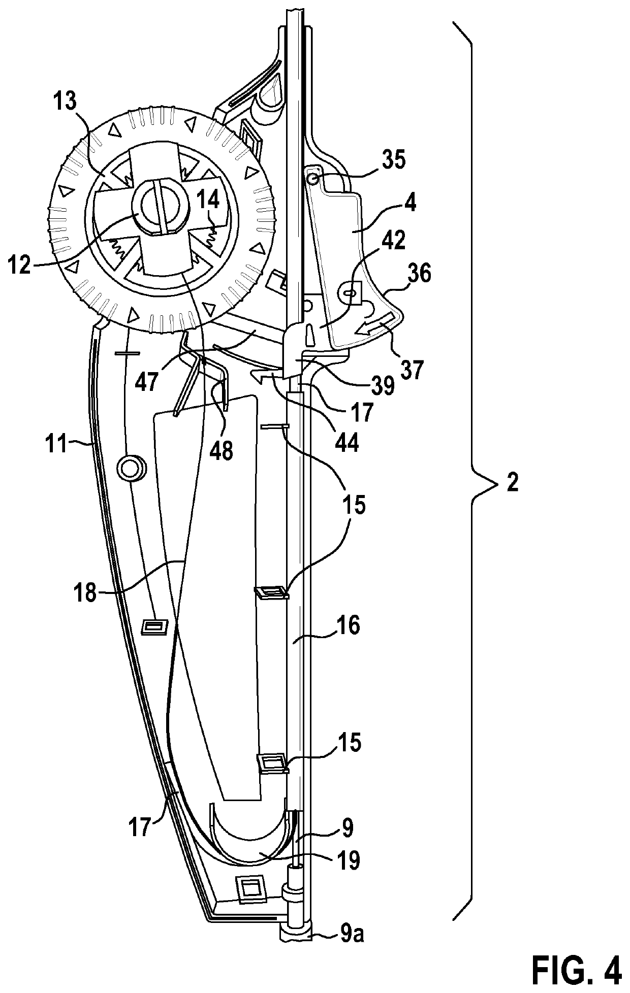
[0019]A preferred handle according to the invention also has the advantage that a winding of the pull cable around the inner shaft is prevented due to the arrangement of the pull cable and the inner shaft in separate openings (lumen) of the brake hose. In addition, the inner shaft is guided by the brake hose and the sleeve during the release, for example, of a stent at the distal end of the catheter (catheter tip). This stabilises the inner shaft. The pull cable is preferably formed as a pull wire. The pull cable is fixedly arranged in the first opening of the brake hose and is thus connected to the brake hose.

[0020]The sleeve preferably has a length (dimension in the longitudinal direction of the sleeve), which is greater than the length of the implant to be released. This means that the sleeve can protrude beyond the distal end of the handle. For example, the implant can be a self-expanding extent. In systems suitable for a stent up to 200 mm long, the overall length (handle (appr...


PUM


Abstract

A handle for a catheter having an inner shaft and a retractable shaft. The handle includes a housing, a pull cable and a release button mounted movably on the housing. A sleeve is secured in the housing and a brake hose is guided movably in the longitudinal direction in a continuous opening of the sleeve. The brake hose has a first continuous opening for arrangement of the pull cable and a second continuous opening for arrangement of the inner shaft. The brake hose configured and arranged such that its position relative to the sleeve in a first state is fixed by the release button, and such that the brake hose in a second state is displaceable after actuation of the release button together with the pull cable in the longitudinal direction of the sleeve and relative to the sleeve and the inner shaft in the proximal direction in order to retract the retractable shaft, such that the retractable shaft can be connected to the pull cable.

Description

PRIORITY CLAIM[0001]This application is a 35 U.S.C. 371 US National Phase and claims priority under 35 U.S.C. § 119, 35 U.S.C. 365(b) and all applicable statutes and treaties from prior PCT Application PCT / EP2018 / 059011, which was filed Apr. 9, 2018, which application claimed priority from European Application EP 17169996.0, which was filed May 8, 2017.FIELD OF THE INVENTION[0002]The invention relates to a handle for a catheter having an inner shaft and a retractable shaft, wherein the handle has a housing and a release button mounted movably on the housing.BACKGROUND[0003]Catheters are generally understood to be tubes or hoses of different diameter made of different materials, by which hollow organs such as the bladder, stomach, intestine, blood vessels or the heart can be probed, emptied, filled, flushed or otherwise treated in a minimally invasive manner. The tubular or hose-like portion of the catheter to be introduced into the body of a human or animal that is to be treated is ...

Claims


Application Information

Patent Timeline
Patent Type & Authority Applications(United States)
IPC IPC(8): A61F2/962
CPCA61F2/962A61F2002/9517A61F2/9517A61F2/966
Inventor WESTHOFF, FELIXROTHFUCHS, NURIA
Owner BIOTRONIK AG
Why Eureka
Try Eureka