Rolling screw

a technology of rolling screw and screw head, which is applied in the direction of gearing, gearing elements, hoisting equipment, etc., can solve the problems of threading subjected to threading, not possessing function precision, and not being efficien

Inactive Publication Date: 2011-04-12
ARES ENG SRL
View PDF12 Cites 1 Cited by
  • Summary
  • Abstract
  • Description
  • Claims
  • Application Information

AI Technical Summary

Benefits of technology

[0022]by means of the synchronisation of the rotation of the elements coupled on the thread, obtained in a simple, economical and reliable manner, which can be realised by means of common machine tools and known processing techniques, through a particular conformation of the thread of at least one of the two elements coupled on the thread; in fact any synchronisation system that imposes a fixed and constant ratio between the number of screw revolutions and that of the nut screw or the roller, prevents travel irregularity and fixes the travel per revolution at a known value, regardless of the loads and frictions present;
[0023]by means of a coupling system between the threads that minimise losses due to friction;
[0024]by means of a threading profile that minimises losses due friction and improves thread resistance;
[0025]by means of a surface hardening treatment that reduces losses due to friction, and wear on the coupled threads.

Problems solved by technology

In particular, in the document U.S. Pat. No. 3,730,016, there is a variation device for linear travel by screw revolution according to load: however this does not possess function precision, is not efficient and the under maximum loads the threading is subjected to stress in proximity to the crest, which represents the weakest zone.
None of the known systems, lacking synchronisation, guarantee constant and accurate travel for each revolution of the control shaft, regardless of the external load and the construction and assembly tolerances of the device.
None of the cited documents performs a precise analysis of the screw / nut screw coupling, the contact points, and the causes of the poor efficiency caused by the threading profile.

Method used


Image

  • Rolling screw
  • Rolling screw
  • Rolling screw

Examples


Embodiment Construction

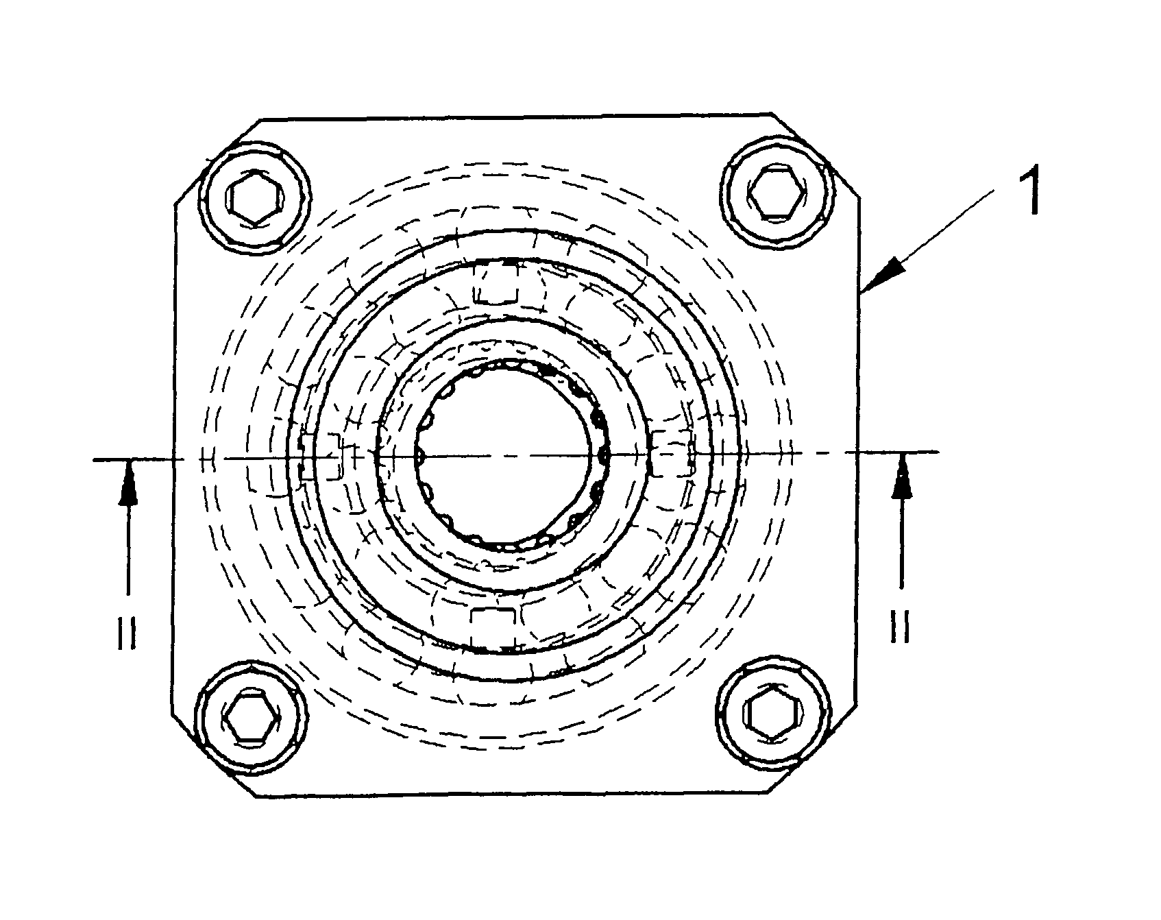
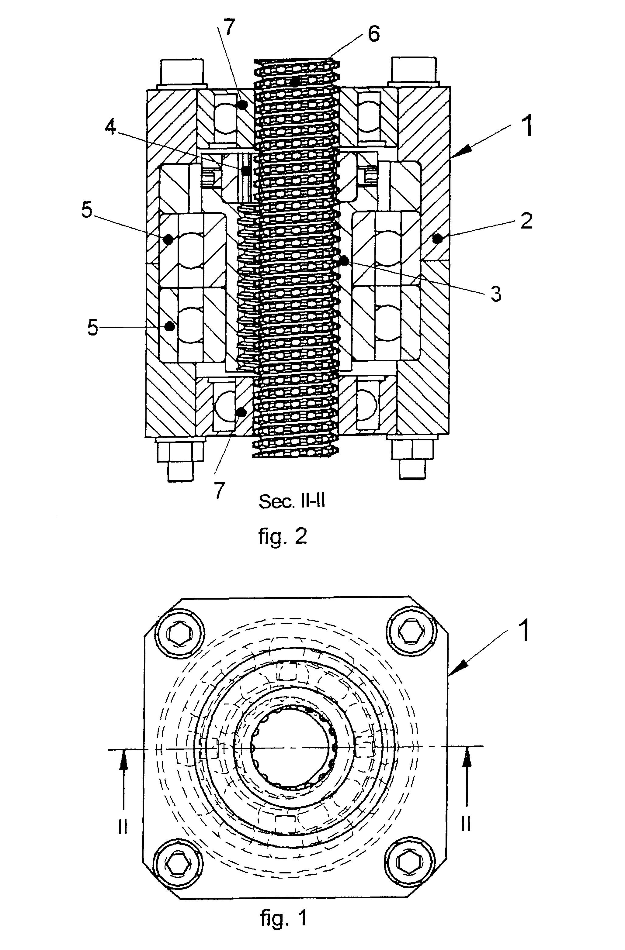
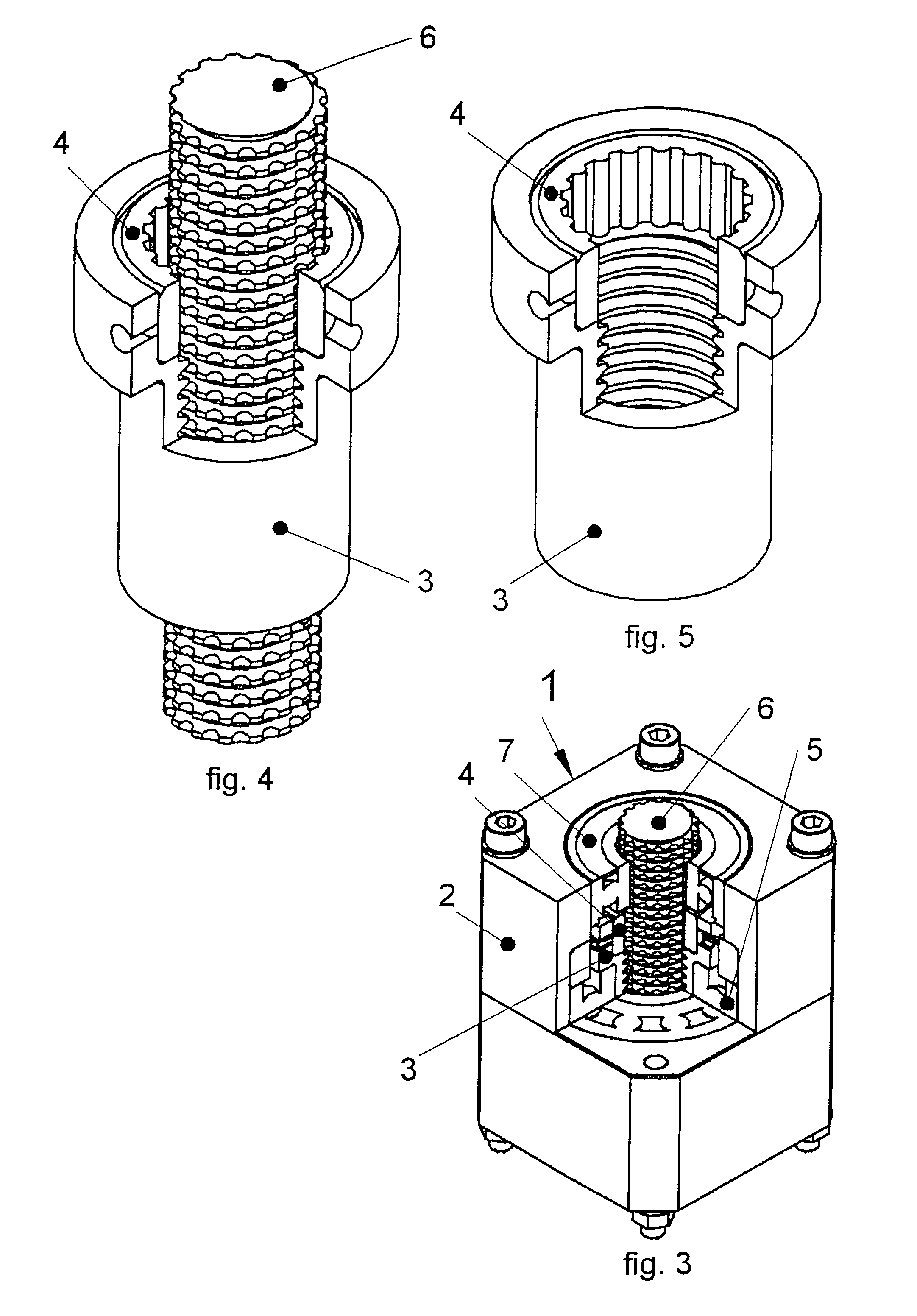
[0054]With particular reference to the mentioned figures, a first, preferred, but not exclusive embodiment of the device according to the finding, identified throughout by the numeral 1 (FIGS. 1, 2, 3) is described. The device results as being particularly advantageous for the conversion of the rotary motion in linear motion with regular movement, accurate positioning, high efficiency levels, low torque, required for the command.

[0055]Device 1 comprises a body or housing 2 of the various members, composed of two parts united by screws, a nut screw 3 equipped with a ring gear 4, two nut screw support bearings 5, a screw 6 with a toothed thread crest, guided in the axial run by two guide bearings 7. The guide bearings 7 present a hole with the same nominal diameter as screw 6; screw 6 is inserted in the hole with a very slight clearance, in order to permit axial sliding. Screw 6 has a threading with a nominal diameter lower than that of the nut screw 3. The nut screw 3 is mounted ecce...


PUM


Abstract

Rolling screw (1) comprising a first threaded male member (6), a second threaded member (3), means (5) that permit said second threaded member (3) to rotate freely in relation to the housing (2), as well as means (7) that permit to maintain fixed and constant the position of the axis of said first threaded member (6) in relation to the housing (2). Means of synchronization are also foreseen for the relative rotation between said first member (6) and said second member (3). Said screw is characterized in that at least one of the two threaded members presents a threading conformation such to permit the transmission of the rotation motion to another element without relative tangential sliding action.

Description

[0001]The present finding relates to a roller screw, according to the general part of claim 1.BACKGROUND ART[0002]On the linear actuators composed of one or more threaded nut screws or threaded male rollers, against whose thread a screw is turned having the same thread step (or a step equal to a complete multiple or fraction, whose inverse is an integer) already described in other documents (U.S. Pat. No. 3,395,385, U.S. Pat. No. 3,730,016, U.S. Pat. No. 3,756,092), the following problems have been detected:[0003]Impossibility of guaranteeing a linear movement proportional to the number of screw revolutions;[0004]irregular travel velocity when the axial load of the screw drops to minimum values, due to the blocking of the nut screw bearings which are not sufficiently loaded, and to the sliding of the screw on the blocked nut screw: this provokes a travel with an irregular step and at most, equal to the threading step;[0005]low efficiency, due to the use of inadequate thread profiles...

Claims


Application Information

Patent Timeline
Patent Type & Authority Patents(United States)
IPC IPC(8): F16H1/24F16H55/02
CPCF16H25/229Y10T74/19805Y10T74/19809F16H2025/2096
Inventor BRUN
Owner ARES ENG SRL
Why Eureka
Try Eureka