Wearable tissue viability diagnostic unit

Inactive Publication Date: 2005-02-10
GRAHAM JOHN S +2
View PDF18 Cites 88 Cited by
  • Summary
  • Abstract
  • Description
  • Claims
  • Application Information

AI Technical Summary

Benefits of technology

[0017] In one or more various implementations, related systems include but are not limited to circuitry and/or programming for effecting the foregoing-referenced method embodiments; the circuitry and/or p

Problems solved by technology

Furthermore, the wearable device

Method used


Image

  • Wearable tissue viability diagnostic unit
  • Wearable tissue viability diagnostic unit
  • Wearable tissue viability diagnostic unit

Examples


Embodiment Construction

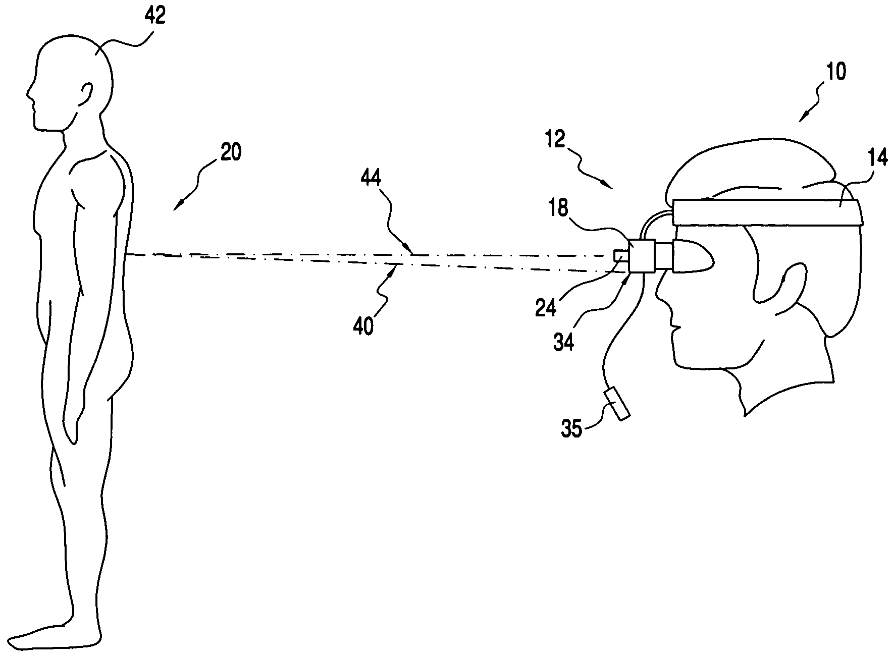
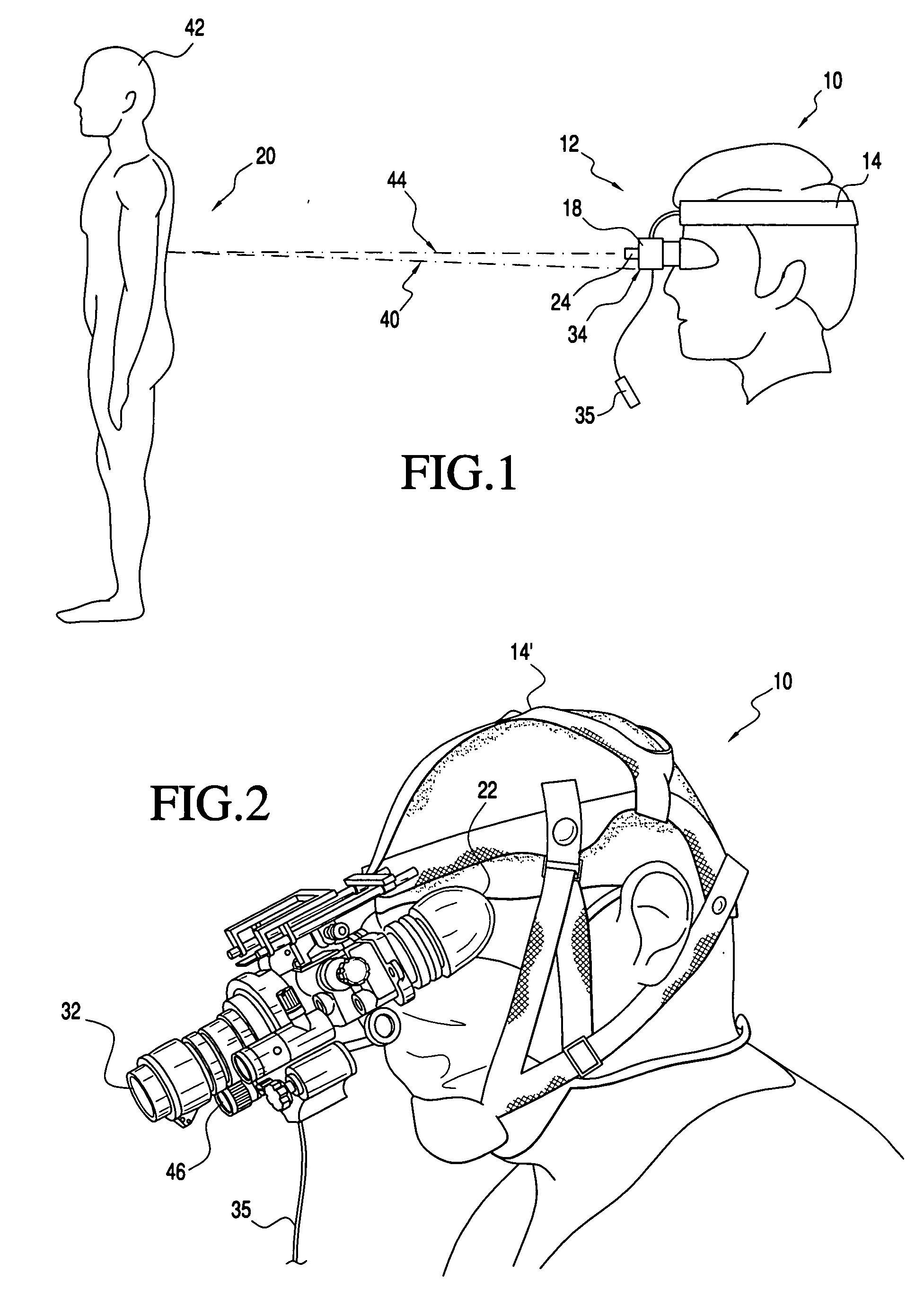
[0029] With reference to the figures, and with reference now to FIG. 1, shown is health care provider 10 using wearable device 12. The wearable device 12 may include a body mounting device (or gear) 14 (means for wearing) that allows the device to be worn on any part of the body for hands-free operation including, but not limited to the head, shoulder, chest or waist. For example, the body mounting device 14 may be a head mounting device as shown in FIGS. 1(14) and 2(14′). In other exemplary embodiments, the device 12 does not include mounting device 14. Thus, a surgeon may operate with the device 12 mounted on his / her head, observing tissue perfusion in areas of interest (tissue region 20) to make a decision on whether or not a particular area, for example, needs to be deeply excised or regrafted. The tissue region 20 may be any in vivo or in vitro tissue region including, but not limited to cells, growths, tumors, other tissues of interest, or tissues of a human or animal body org...


PUM


Abstract

A device for gathering image information about a region of tissue that has been exposed to a contrast agent and methods of use thereof. The device preferably includes night vision goggles, and an excitation source that generates light of a wavelength to activate the contrast agent. The excitation source preferably is attached to the night vision goggles and is capable of directing light to a target. A filter preferably is attached to the night vision goggles, wherein the filter passes light sufficient to form an image of the region of tissue, and wherein the image may be assessed to determine the viability of the region of tissue.

Description

II. CROSS-REFERENCE TO RELATED APPLICATION [0001] This patent application claims the benefit of U.S. Provisional Patent Application No. 60 / 484,784, filed Jul. 2, 2003, which is hereby incorporated by reference.I. STATEMENT OF GOVERNMENT INTEREST [0002] The United States' Army has certain rights in this invention.III. FIELD OF THE INVENTION [0003] The present invention relates to medical diagnostic tools. More particularly, the present invention relates to a wearable device for assessing the viability of a tissue region. IV. BACKGROUND OF THE INVENTION [0004] Medical diagnostic tools include processes and / or devices that assist people and / or other processes and / or devices in the assessment of medical conditions. One type of medical condition in which medical diagnostic tools prove particularly useful involves determining the viability of a tissue region. This may be the case, for example, in medical procedures involving skin grafting and / or burns to the skin. Presently, one approach ...

Claims


Application Information

Patent Timeline
IPC IPC(8): A61BA61B5/05A61B5/103A61B6/00
CPCA61B5/0071A61B5/445A61B5/444
Inventor GRAHAM, JOHN S.BUA, DOMINIC P.SCHOMACKER, KEVIN T.
Owner GRAHAM JOHN S
Why Eureka
Try Eureka