

Electrophysiological intuition indicator
- Summary
- Abstract
- Description
- Claims
- Application Information
AI Technical Summary
Problems solved by technology
Method used
Image

Examples
Embodiment Construction
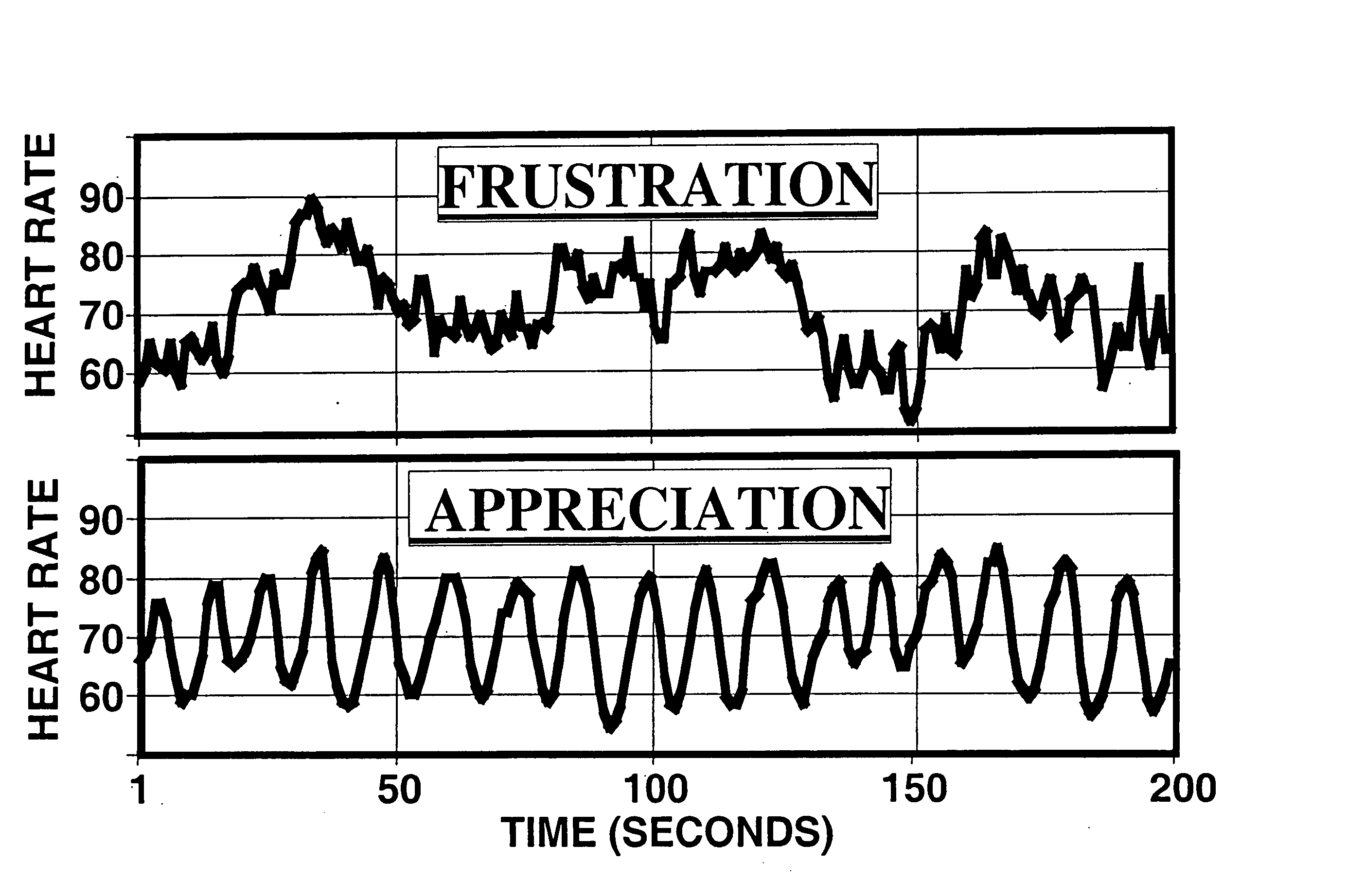
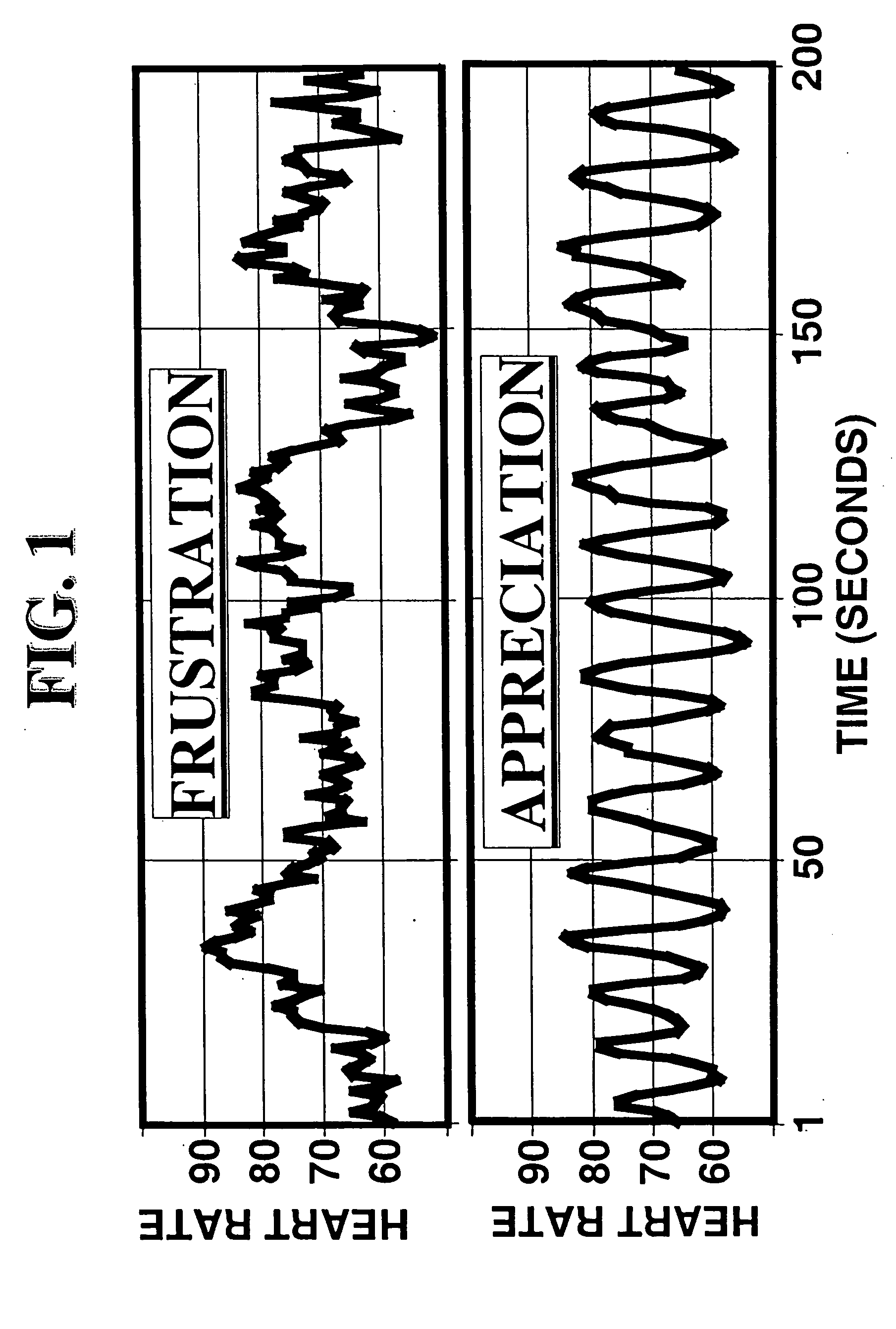
[0021] System and methods for electrophysiological detection and measurement of electrophysiological intuition indicators are disclosed. In one embodiment, one or more electrophysiological properties of an individual are monitored and used as an indication of an unknown or future event. In one embodiment, the electrophysiological property is the individual's HRV (heart rate decelerations and accelerations), while in other embodiments it may be the individual's brain wave activity as measured by an electroencephalogram (EEG), respiration pattern, skin conductance level (SCL), etc. One aspect of the invention is to utilize one or more electrophysiological properties of a group of individuals as a predictive tool for certain future events, such as investment decisions, gambling, etc.
[0022] In one embodiment, a “signal averaging” technique is a digital technique for separating a repetitive signal from noise without introducing appreciable signal distortion is used to detect EEG activit...
PUM
 Abstract
Description
Claims
Application Information