Locking cap assembly for spinal fixation instrumentation

Inactive Publication Date: 2005-02-10
DEPUY ACROMED INC
View PDF29 Cites 108 Cited by
  • Summary
  • Abstract
  • Description
  • Claims
  • Application Information

AI Technical Summary

Benefits of technology

[0006] One or more of these and other desirable traits are achieved in accordance with the present invention by a fixation assembly wherein a closure cap fits over an opening to close a rod-receiving slot of a fixation screw, hook, post or other anchor assembly, and capture the rod therein. A set screw can be threaded through the cap and tightened against the rod to further clamp it in the assembly. In one embodiment, the closure cap extends over and around the head of the rod-receiving assembly, which may, for example include a slotted shaft, post or head, and the cap is adapted to lock together therewith by limited rotation. This may be accomplished in one embodiment construction by arranging the cap to have a set of sector rim protrusions positioned to fit through a corresponding set of protruding bosses or partial flange segments located on the head, and to rotate into opposition therewith for securing the cap onto the top of the fixation screw. The protrusions or flange segments are angled, along the radial direction, so that they bear against each other and jam when rotated, thus cannot slip out of engagement. The opposed segments tighten and lock the cap against the head when the cap is rotated through a

Problems solved by technology

This latter construction involves no rotation of threaded members, but has the disadvantage that a certain amount of unobstructed lateral space along the rod adjacent to the connection point is necessary for the sliding installation of the closure cap.
Furthermore, the cap inserts o

Method used


Image

  • Locking cap assembly for spinal fixation instrumentation
  • Locking cap assembly for spinal fixation instrumentation
  • Locking cap assembly for spinal fixation instrumentation

Examples


first embodiment

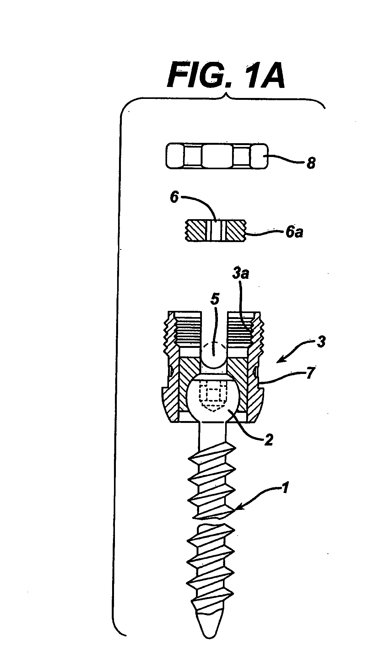
[0022]FIG. 2 illustrates an anchor screw assembly 31 of the present invention. As shown, the anchor screw assembly 31 includes a screw 32 and a top member 33 which may be integral with the screw or, like the prior art construction of FIG. 1A, may be a separate head member that secures to the proximal end of the screw 32. The top member 33 includes a slot indicated generally by 34 for receiving a rod, and contains at its uppermost region 35, a plurality of segmented or partial flange members 36a, 36b, 36c, 36d which extend radially outward from its perimeter and have respective slots or spaces 37a, 37b therebetween. As further shown in FIG. 2, each of the flange segments 36a, 36b, 36c, 36d has a lower surface 38, as best seen in the end views of flange segments 36a and 36c, that engages a closure cap 40 (FIGS. 3A-3C). While not shown, one or more of the flange segments or cap may include a notch, detent or catch or a jamming feature, to prevent rotation in the opposite sense.

[0023] T...

embodiment 50

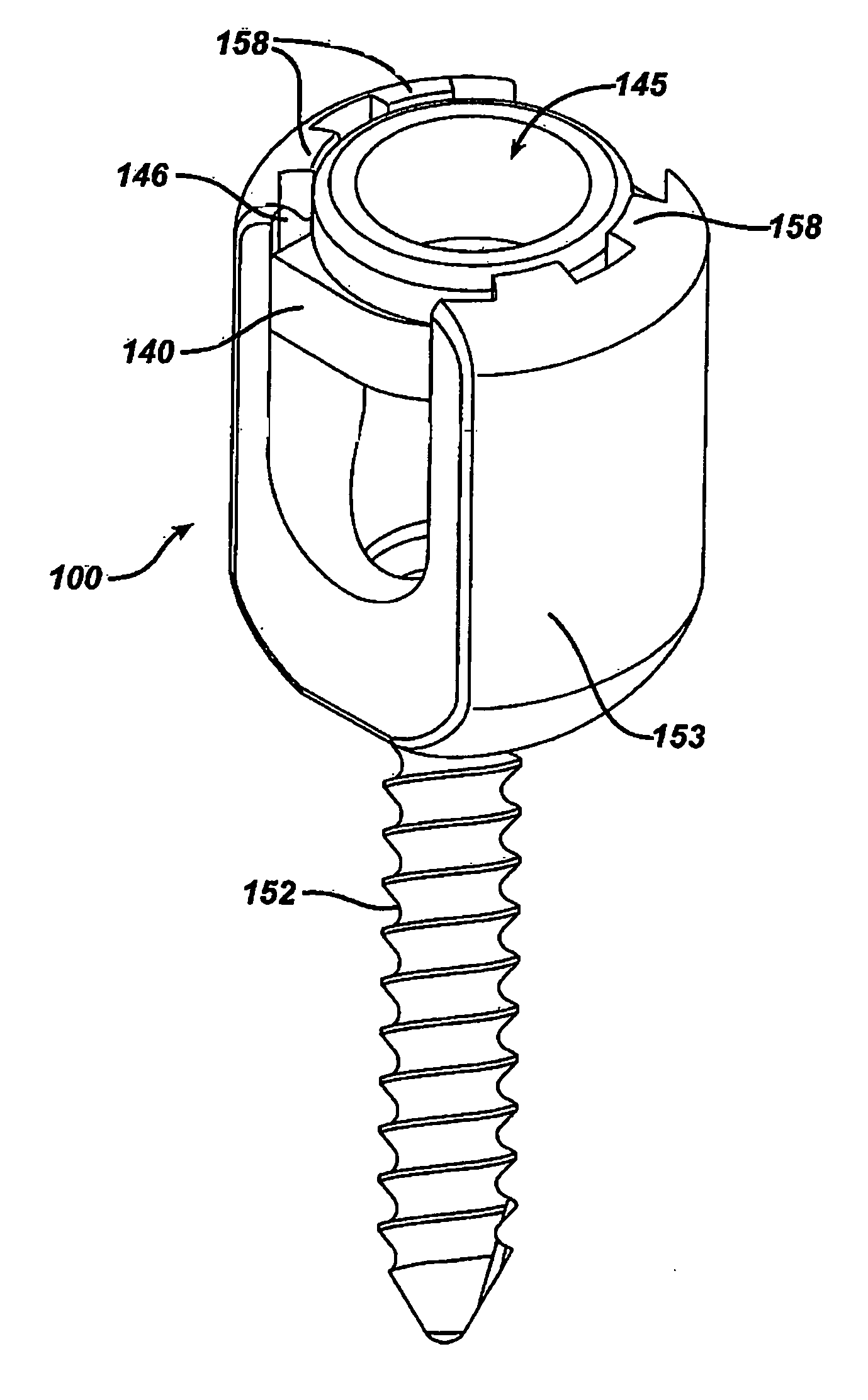
[0026] Such an embodiment 50 is shown in FIG. 4. In this embodiment, the head 53 of the anchor assembly has a pair of reduction tabs 55 extending upwardly from the sides of the slot. In this case, the invention contemplates a closure cap 60 with a rim-engaging securing structure similar to that of cap 40 for engagement by a small rotational motion, but the cap structure further includes a pair of arcuate slots 62a, 62b located in its central region and sized for passage of the reduction tabs 55 or other protruding head structure therethrough. Each of the slots 62a, 62b extends past the edges of the tabs 55, permitting sufficient rotation of the cap to lock the cap in position. The structure of the cap itself strengthens or supports both the surrounding wall of the rod receiving slot, and the thin-walled tabs 55 which rise therefrom, while leaving the central on-axis region above the cap entirely unobstructed for insertion, for example, of a set screw along an axial direction, and pe...


PUM


Abstract

An assembly such as an anchor screw, bone plate, offset hook, post, transverse connector or other spinal anchor for anchoring to bone and clamping a linkage such as a rod, wire cable or the like. The assembly has a top member with an open slot to receive the linkage, and a twist-lock closure cap to close the open end, capturing the linkage in the slot. One closure cap fits over and around the top member, with a set of segmented protrusions that extend through a corresponding set of protruding flange segments spaced about the circumference of the top member. The cap is configured to rotate and lock against the top member like a flange-locking bayonet mount when turned through a limited degree of rotation. Slots may be provided through the face of the closure cap allowing reduction tabs to project through the cap, and the locking cap may be adapted to a range of screw, eye, hook, post, connector and other anchor assemblies to securely clamp the linkage by use of a rotation tool disposed along an access path aligned with the axis of the screw, thus requiring no lateral clearance along the longitudinal direction of the linkage element. Locking is effected by a set screw that passes through the cap and tightens against the linkage to firmly immobilize it in the anchor assembly. Another cap embodiment fits into the center of the head with a partial twist locking motion. Opposed locking surfaces prevent slippage in the radial direction, and a sloping contact floor surface may apply torque to further increase pressure on urge mating detent features in an adjacent wall.

Description

CROSS REFERENCE TO RELATED APPLICATION [0001] This application is a continuation of U.S. patent application Ser. No. 09 / 667,937 to Bono et al., filed on Sep. 22, 2000, and entitled “Lock Cap Anchor Assembly for Orthopaedic Fixation,” which application is incorporated herein by reference in its entirety.BACKGROUND OF THE INVENTION [0002] The present invention relates to orthopedic fastening systems and to mechanisms for securing and locking a linking or stabilizing element, such as a rod, to a bone screw having a slotted head that receives the rod therein. It also relates to structures or anchor assemblies having such a slotted or open head for receiving a rod, wherein the slotted portion extends from a hook, plate, bracket or positioning arm. [0003] A number of such structures are known. Thus, for example, the widely used Harms T-plate used for stabilizing the cervical vertebrae has a projecting slotted bolt adapted to receive a rod or cable through the slot and clamp down by screwi...

Claims


Application Information

Patent Timeline
IPC IPC(8): A61B17/58A61B17/70A61B17/84
CPCA61B17/7032A61B17/7035Y10S606/907A61B17/7041A61B17/7044A61B17/7037A61B17/70
Inventor BONO, FRANK SCOTTROSS, GEORGE JOSEPHSICVOL, CHRISTOPHER WERNERBURGESS, IAN
Owner DEPUY ACROMED INC
Why Eureka
Try Eureka