Landing-control device and landing-control method for aircraft

a technology for landing control and aircraft, which is applied in adaptive control, navigation instruments, instruments, etc., can solve the problems of damage to the body of the aircraft, difficulty in performing automation of control, and difficulty in speed control of the aircraft in the vertical direction,

Inactive Publication Date: 2005-02-10
SUBARU CORP
View PDF11 Cites 56 Cited by
  • Summary
  • Abstract
  • Description
  • Claims
  • Application Information

AI Technical Summary

Problems solved by technology

However, with respect to this type of aircrafts, the merit that no limitation is imposed on any landing place rather makes it difficult to perform automation of control.
For example, in the case of landing on a landing surface such as a ship deck, the landing surface swings due to a wave surface, and thus the speed control of the aircraft in the vertical direction is more difficult than in the case of landing on a static landing surface.
This is because if the speed control fails, an impact of the landing is intensified (a hard landing state), resulting in damage of the body of the aircraft.
Furthermore, since the wave surface is irregular, it is difficult for a conventional control technology to estimate the wave surface for the control, and thus there is no other way to rely on than a manual operation of an experienced operator.

Method used


Image

  • Landing-control device and landing-control method for aircraft
  • Landing-control device and landing-control method for aircraft
  • Landing-control device and landing-control method for aircraft

Examples


Embodiment Construction

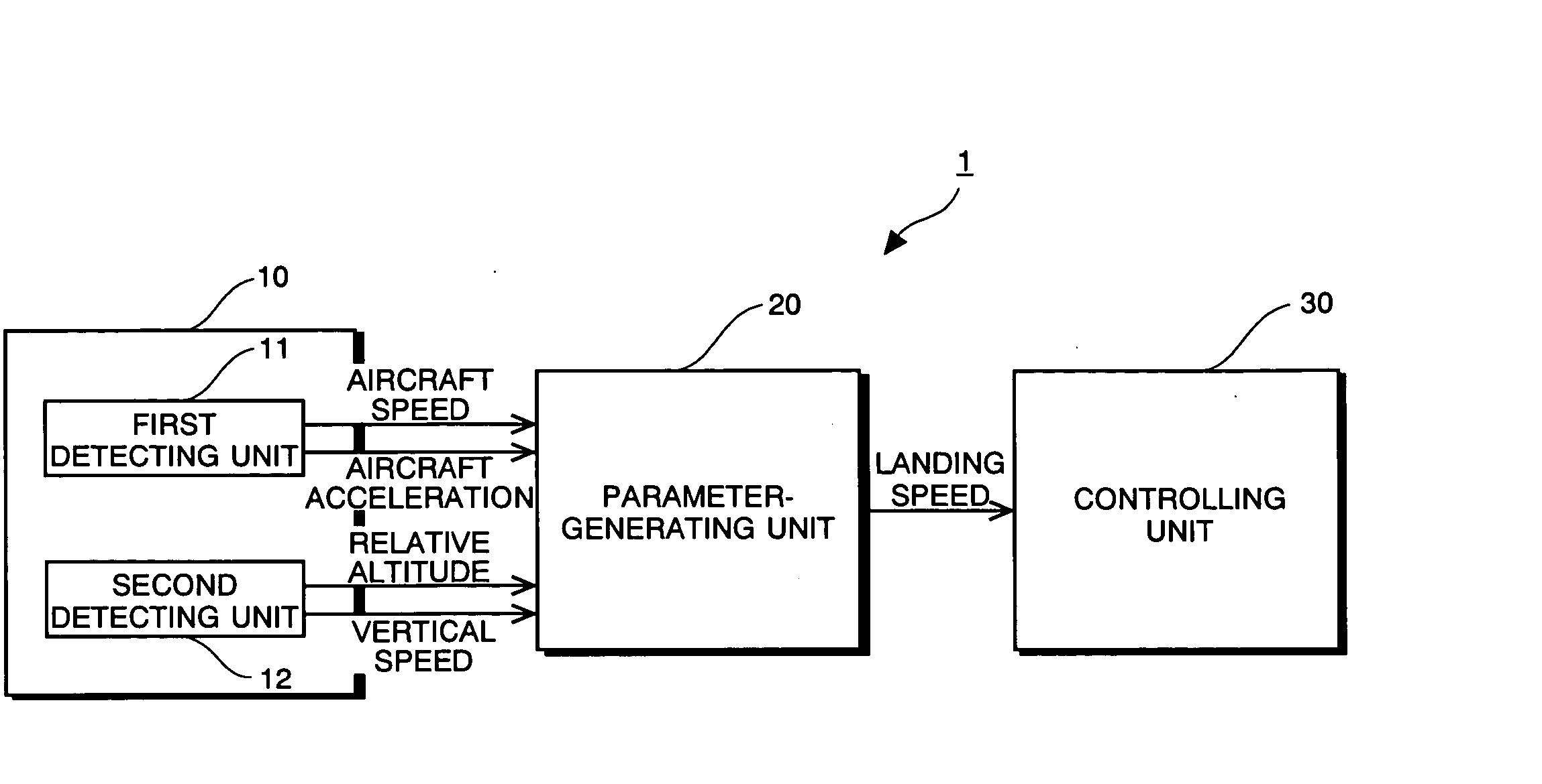
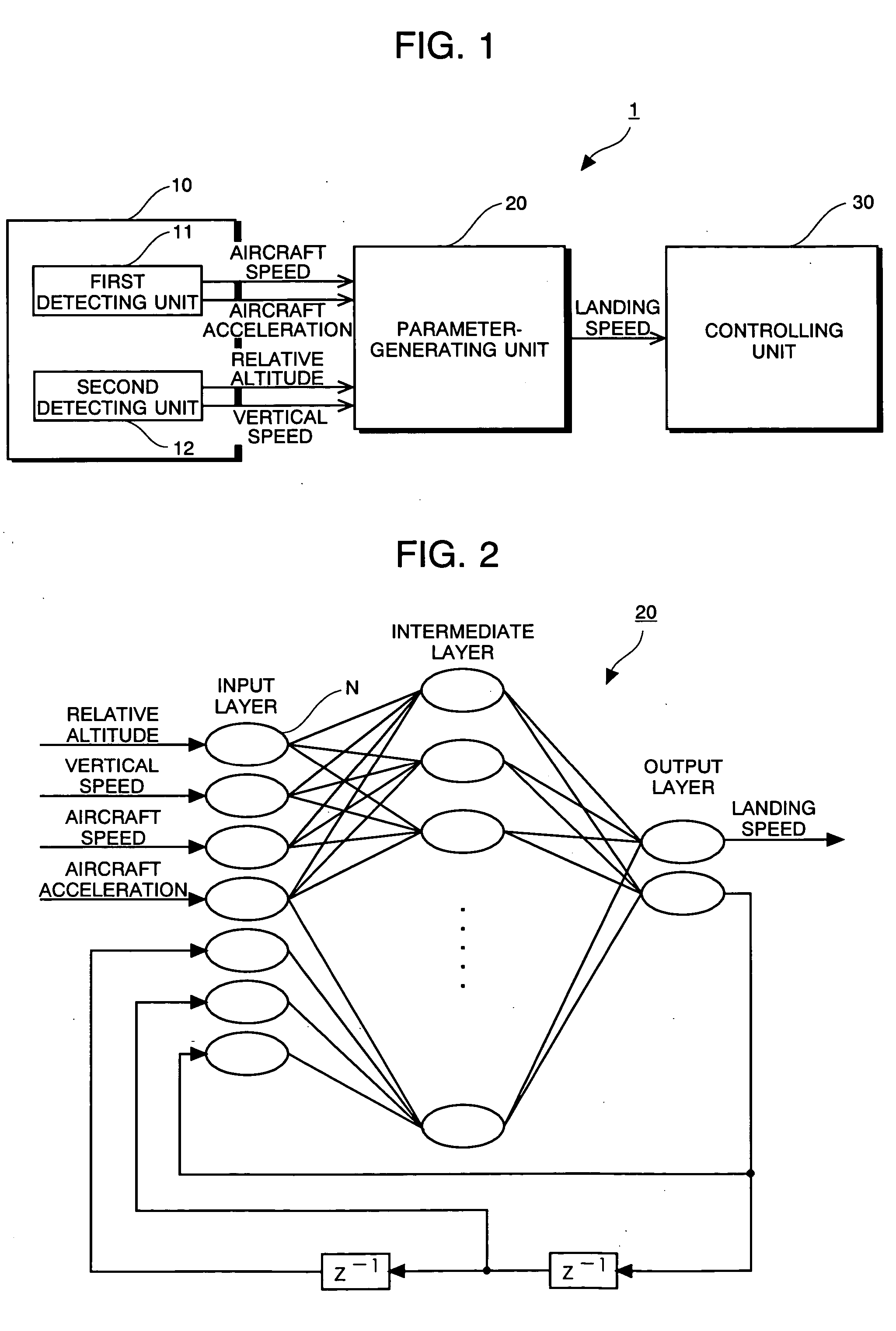
[0022]FIG. 1 is a block diagram showing the construction of a landing-control device for an aircraft according to a present embodiment. The landing-control device 1 is installed in a vertical takeoff and landing aircraft (hereinafter referred to as an “aircraft”) such as a helicopter or the like, and carries out the speed control of the aircraft in the vertical direction during landing. The landing-control device 1 comprises a detecting unit 10, a parameter-generating unit 20 and a controlling unit 30.

[0023] The detecting unit 10 comprises a first detecting unit 11 for detecting a condition of an aircraft and a second detecting unit 12 for detecting the relative relationship between the aircraft and a landing surface. For example, an accelerometer is used as the first detecting unit 11, and an acceleration of the aircraft in the horizontal direction (hereinafter referred to as an “aircraft acceleration”) is detected by the first detecting unit 11. Furthermore, the first detecting u...


PUM


Abstract

A landing-control device is provided having a new structure for carrying out landing control of an aircraft. A detecting unit 10 detects at least a relative altitude from a landing surface to an aircraft. A parameter-generating unit 20 is constructed by a neural network having a feedback loop which receives a detection value detected by the detecting unit 10 and outputs a landing-control parameter of the aircraft, an output of a first node among plural nodes constituting the neural network being input to a second node different from the first node. A controlling unit 30 controls the aircraft based on the control parameter output from the parameter-generating unit 20.

Description

BACKGROUND OF THE INVENTION [0001] 1. Field of the Invention [0002] The present invention relates to a landing-control device and method for an aircraft, and particularly to control of a vertical speed of landing on a place where a landing surface such as a ship deck that swings with time. [0003] 2.Description of the Related Art [0004] There have been hitherto proposed various control technologies that use a neural network as one of technologies controlling a control target with high precision irrespective of a non-linear element of the control target, external disturbance or a change of an environment over time. According to the neural network, a coupling weight coefficient is properly set in a learning process carried out in advance, so that a required control parameter can be output-based on predetermined input information with high precision. A back propagation method is generally used in the learning process of the neural network. Control using the neural network includes air-f...

Claims


Application Information

Patent Timeline
Patent Type & Authority Applications(United States)
IPC IPC(8): B64D45/04G01S19/29G01S19/30G05B13/02G05D1/06
CPCG05D1/0684
Inventor TEZUKA, SYUNSUKE
Owner SUBARU CORP
Why Eureka
Try Eureka