Light bulb changer/holder apparatus

a technology for changing and holding light bulbs, which is applied in the manufacture of electric discharge tubes/lamps, fixed installations, lighting and heating apparatuses, etc. it can solve the problems of insufficient structure, inconvenient operation, and inability to meet the needs of users, and achieves the effect of convenient operation, low manufacturing cost and sufficient structur

Inactive Publication Date: 2005-02-17
ALBRECHT JOSEPH
View PDF15 Cites 4 Cited by
  • Summary
  • Abstract
  • Description
  • Claims
  • Application Information

AI Technical Summary

Benefits of technology

[0008] Yet another object of the instant invention is to provide an apparatus that can be used as either a light bulb changer or a light bulb holder that is easy to operate and inexpensive to manufacture.
[0009] The objects of the instant invention are accomplished through the use of a one-piece light bulb changer / holder that includes two upwardly extending fingers for securely grasping the bulb. The two fingers are located on opposing sides of the apparatus, and are spaced apart from one another to create a gap equal to, or slightly larger than, the diameter of the bulb. Each finger is curved to conform to the shape of a cylindrical fluorescent bulb, and has an inner diameter slightly smaller than the outer diameter of the bulb. The fingers are constructed of a moldable material such as Acetel plastic, nylon or any other material suitable to provide sufficient structure while simultaneously providing flexibility (or elasticity) of the fingers to engage and disengage the bulb. One finger curves upward clockwise from the base of the apparatus around the bulb to a termination point just past (clockwise) the upper-most point of the diameter of the bulb. The opposing finger curves upward from the base in a counterclockwise manner around the bulb to a termination point just past (counterclockwise) the upper-most point of the diameter of the bulb. The base of the apparatus of the instant invention includes internal threads for removably placing the apparatus on an extension pole.

Problems solved by technology

Nevertheless, few such devices have been designed for use with fluorescent light bulbs, which present unique problems due to their long, narrow shape and relatively large size.
All such prior art devices are extremely complex, difficult to operate, and extremely expensive to manufacture.
This device is cumbersome, requires a considerable amount of skill and dexterity to operate, requires that the changer device be used only on the socket side of spring-loaded fluorescent lamps, and is limited in the length of bulbs that it can accommodate.
Another common problem associated with fluorescent light bulbs involves storage and transportation of the bulbs.
Certain fluorescent light bulbs are extremely expensive, thus avoiding breakage during transportation and storage is imperative.

Method used


Image

  • Light bulb changer/holder apparatus
  • Light bulb changer/holder apparatus
  • Light bulb changer/holder apparatus

Examples


Embodiment Construction

[0023] As required, a detailed embodiment of the present invention is disclosed herein; however, it is to be understood that the disclosed embodiment is merely exemplary of the principles of the invention, which may be embodied in various forms. Therefore, specific structural and functional details disclosed herein are not to be interpreted as limiting, but merely as a basis for the claims and as a representative basis for teaching one skilled in the art to variously employ the present invention in virtually any appropriately detailed structure.

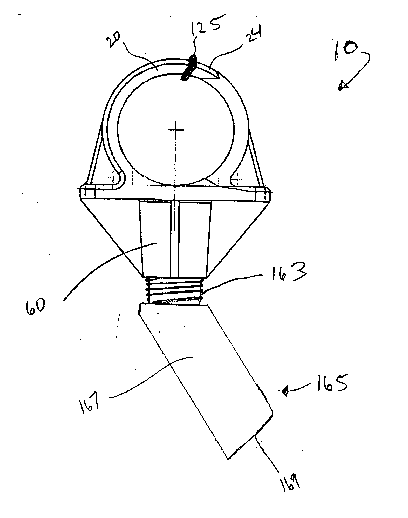
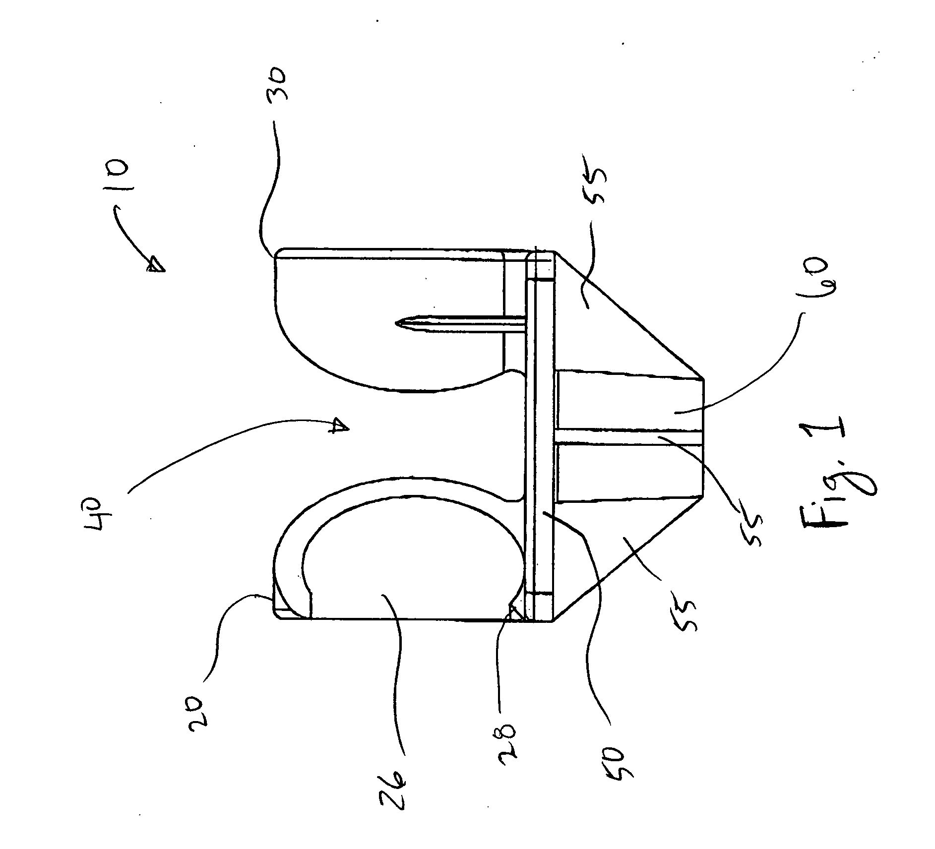
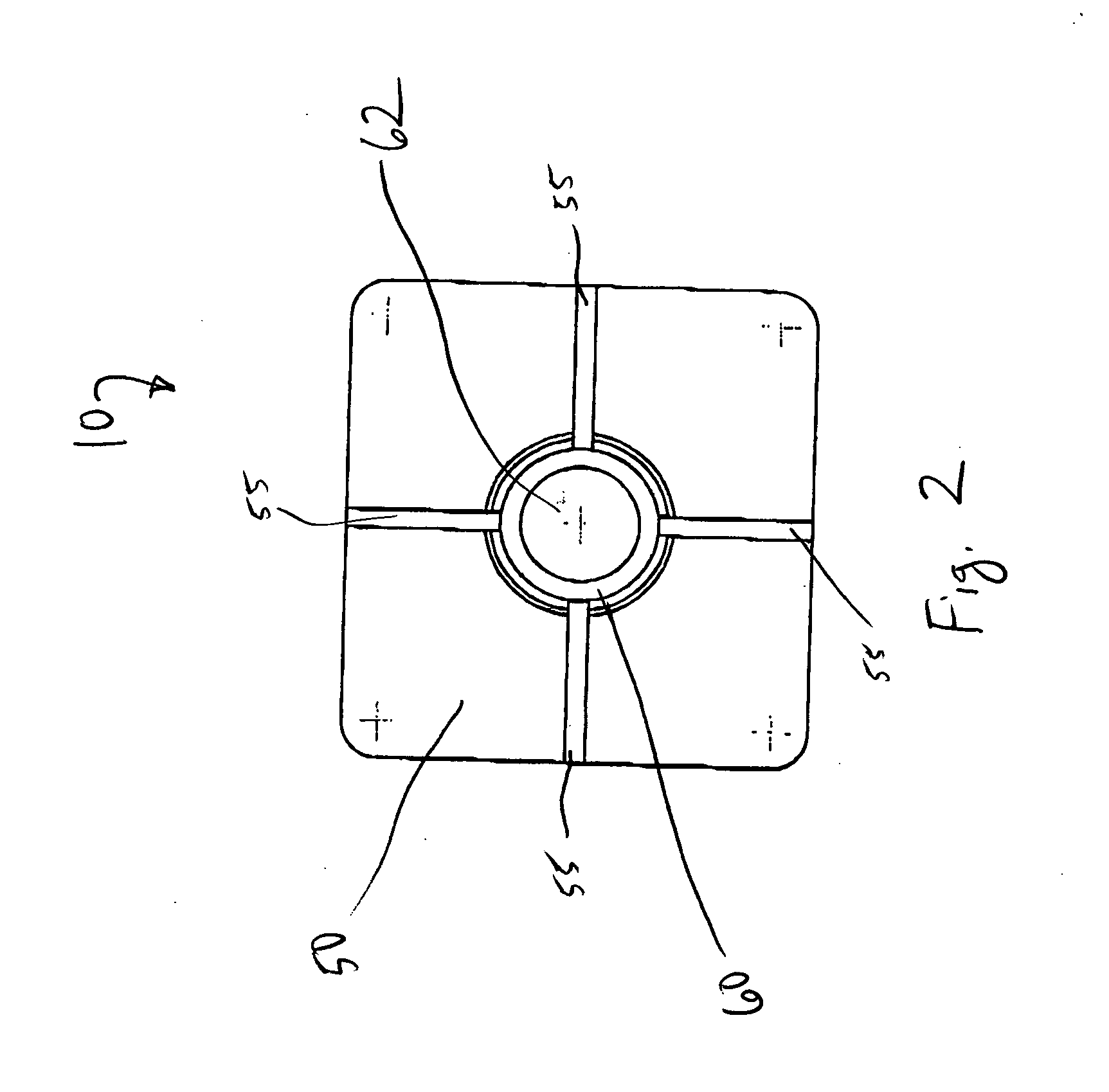
[0024] Referring to FIGS. 1-5, bulb changer / holder 10 is shown including base 50. First hooked finger 20 and second hooked finger 30 each protrude from base 50. First finger 20 and second finger 30 are spaced apart from each other by gap 40. Cylindrical member 60 protrudes downward generally perpendicular to base 50. Angled trusses 55 extend between base 50 and cylindrical member 60 to rigidly support cylindrical member 60 to base 50. As is ...


PUM


Abstract

An apparatus and method for grasping a light bulb is provided. The apparatus includes a pair of opposing fingers protruding from a base. A gap is positioned between the fingers to receive a light bulb, such as a tubular fluorescent light bulb. Once the light bulb is positioned within the gap, the apparatus is rotated and the fingers snap around the outer surface of the light bulb. The fingers are constructed of a generally elastic material to allow the fingers, which have an internal diameter smaller than the diameter of the bulb being grasped, to flex around the outer surface of the bulb. The apparatus includes a threaded cavity for receipt of a male threaded end of an extension pole.

Description

[0001] This application claims priority pursuant to 35 U.S.C. 119(e) to co-pending U.S. Provisional Patent Application Ser. No. 60 / 474,641, filed May 30, 2003, the entire disclosure of which is incorporated herein by reference.FIELD OF THE INVENTION [0002] The present invention relates generally to an apparatus for changing and / or holding light bulbs. More particularly, it is concerned with an apparatus to assist in changing fluorescent light bulbs using an extension pole or other similar extension device. The apparatus of the instant invention can also be utilized without an extension pole as a light bulb holder to safely support a fluorescent light bulb during storage or transport. BACKGROUND OF THE INVENTION [0003] The use of an extension pole to change a light bulb is well known, and numerous examples of such light bulb changers exist in a wide variety of embodiments. Nevertheless, few such devices have been designed for use with fluorescent light bulbs, which present unique pro...

Claims


Application Information

Patent Timeline
Patent Type & Authority Applications(United States)
IPC IPC(8): F21S8/00F21V19/00H01J9/00H01KH01K3/32
CPCH01J9/006F21V19/008
Inventor ALBRECHT, JOSEPH
Owner ALBRECHT JOSEPH
Why Eureka
Try Eureka