Torsion beam type suspension, method for forming torsion beam, and apparatus for forming torsion beam

a technology of torsion beam and suspension, which is applied in the direction of vehicle springs, interconnection systems, transportation and packaging, etc., can solve the problem of increasing the overall weight of a product, and achieve the effect of high twisting rigidity

Active Publication Date: 2005-02-17
DONG HEE IND
View PDF2 Cites 22 Cited by
  • Summary
  • Abstract
  • Description
  • Claims
  • Application Information

AI Technical Summary

Benefits of technology

[0009] The present invention has been made in view of the above drawbacks, and it is an object of the present invention to provide a torsion beam type suspension, wh

Problems solved by technology

The conventional torsion beam configured as stated above inevitably complicates the overall assembly process due t

Method used


Image

  • Torsion beam type suspension, method for forming torsion beam, and apparatus for forming torsion beam
  • Torsion beam type suspension, method for forming torsion beam, and apparatus for forming torsion beam
  • Torsion beam type suspension, method for forming torsion beam, and apparatus for forming torsion beam

Examples


Embodiment Construction

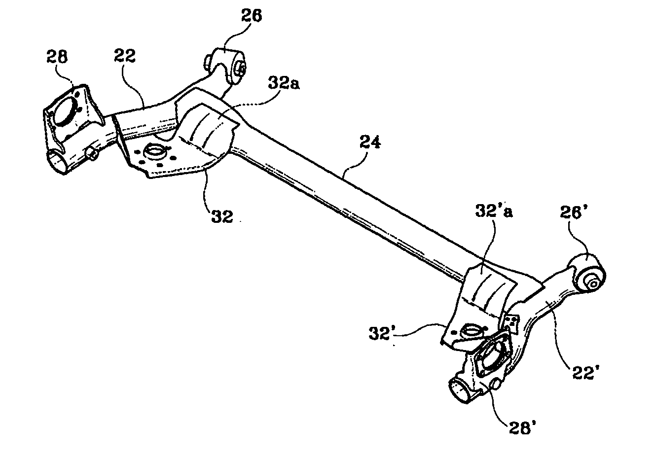
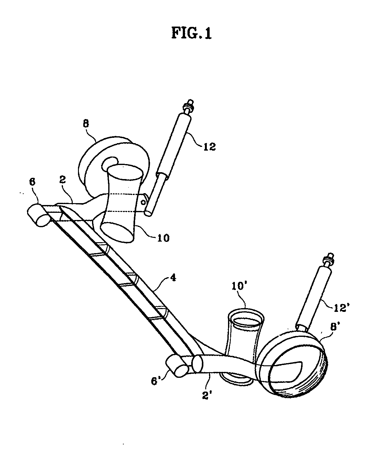
[0026] As shown in FIG. 2, a torsion beam type suspension of the present invention is configured in a fashion such that a pair of left and right trailing arms 22 and 22′ thereof are connected to each other through a torsion beam 24. The front ends of the trailing arms 22 and 22′ are adapted to pivotally support a vehicle body (not shown) by using joints 26 and 26′ having rubber bushes, respectively. Spindle brackets 28 and 28′ are welded to the rear ends of the trailing arms 22 and 22′ for allowing wheels to be coupled to the rear ends of the tailing arms 22 and 22′, respectively. Further, spring seats 32 and 32′ are welded on the trailing arms 22 and 22′ at portions between the joints 26 and 26′ and spindle brackets 28 and 28′ for mounting the suspension springs. The configuration of the wheels, suspension springs, shock absorbers, and the like are the same as those shown in FIG. 1.

[0027] The trailing arms 22 and 22′ are formed in the shape of a bent pipe.

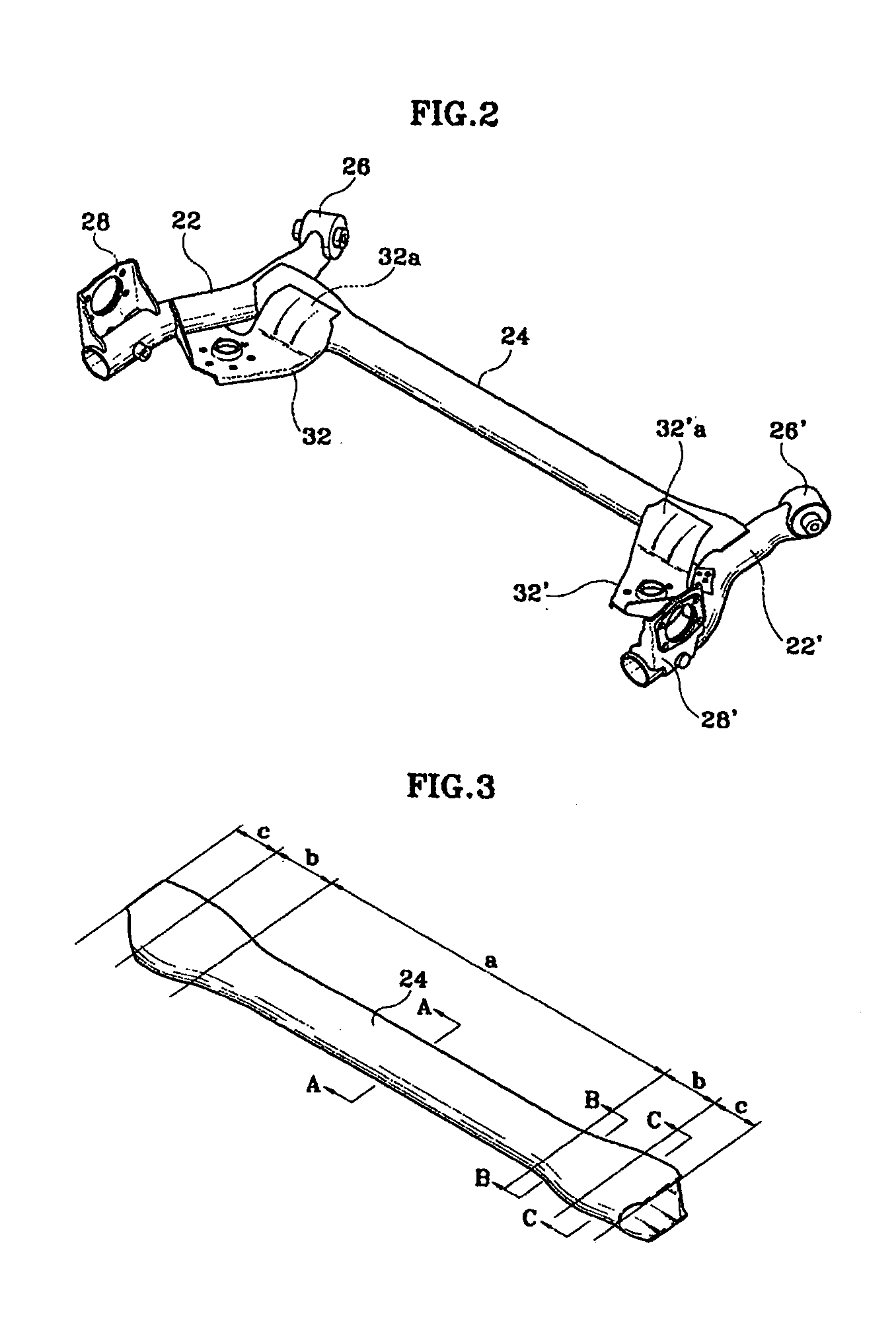
[0028] The torsion beam ...


PUM

PropertyMeasurementUnit
Lengthaaaaaaaaaa
Thicknessaaaaaaaaaa
Pressureaaaaaaaaaa

Abstract

A torsion beam type suspension and a forming method of a torsion beam are disclosed. In the torsion beam type suspension comprising a pair of left and right trailing arms connected to each other through a torsion beam, front ends of the trailing arms being used to mount a vehicle body by using joints, the torsion beam is obtained by forming an overall length of a pipe having a certain wall thickness by using a pressure forming process. In this case, end sections defined at both end portions of the torsion beam have a cross-sectional shape of a hollow oval, a center section defined at a center portion of the torsion beam has a cross-sectional shape of a hollow open loop, and middle sections defined between the center portion and both the end portions of the torsion beam have a cross-sectional shape of a hollow open loop. The loop of the middle sections defines an inner space larger than that defined by the loop of the center section. Further, since the torsion beam can be easily formed by adopting a hydro-forming process, it is possible to achieve high twisting rigidity, bending rigidity, and durability without requiring a torsion bar and reinforcement, which must be inevitably assembled to a conventional torsion beam axle, resulting in a reduction of the number of constitutive elements and the overall weight.

Description

FIELD OF THE INVENTION [0001] The present invention relates to a torsion beam type suspension, a method for forming a torsion beam, and an apparatus for forming a torsion beam. BACKGROUND OF THE INVENTION [0002] Suspensions for motor vehicles are devices used to connect a vehicle body and wheels to each other, and are adapted to absorb shock and vibration applied from the road during movement, thereby improving ride comfort and stability of motor vehicles. Such suspensions are basically classified into integral type suspensions wherein left and right wheels are connected by an axle, and independent type suspensions wherein left and right wheels operate individually. [0003] The suspensions comprise springs for absorbing shock from the road, shock absorbers adapted to restrict free vibration of the springs, arms or links for controlling the operation of wheels, and the like. [0004] There is another type of suspension—torsion beam type suspension—configured in a fashion such that a pai...

Claims


Application Information

Patent Timeline
IPC IPC(8): B60G21/05
CPCB60G21/051B60G2202/12B60G2202/136B60G2204/1244Y10T29/49622B60G2204/43B60G2206/20Y10T29/49805B60G2204/1246
Inventor OK, CHOONG-SUKHAN, SUNG-WOOKPARK, SOON-HYUNLEE, JONG-RAEPARK, KEUN-JAE
Owner DONG HEE IND
Why Eureka
Try Eureka