Power converter apparatus and method for controlling the same

a technology of power converter and ground fault, which is applied in the direction of emergency protective circuit arrangement, and emergency protection circuit arrangement for limiting excess voltage/current, etc., can solve the problems of unnecessarily interrupting temporarily stopping the electric supply to the device in both apparatuses, and not working effectively

Inactive Publication Date: 2005-02-17
TOYOTA IND CORP
View PDF3 Cites 41 Cited by
  • Summary
  • Abstract
  • Description
  • Claims
  • Application Information

AI Technical Summary

Problems solved by technology

Thus, when a ground-fault actually occurs, the ground-fault circuit interrupter 36 may not function effectively.
However, the electric supply to the device is temporarily stopped in both apparatuses even if the ground-fault circuit interrupter is normal.
That is, in the conventional apparatuses, the electric supply to the device is unnecessarily interrupted.
Therefore, the electric motor is unnecessarily stopped and resumed.
The same problem arises when using power converters other than the inverter apparatus, such as a DC / DC converter and an AC / DC converter, with the power source for electric device.

Method used


Image

  • Power converter apparatus and method for controlling the same
  • Power converter apparatus and method for controlling the same
  • Power converter apparatus and method for controlling the same

Examples


Embodiment Construction

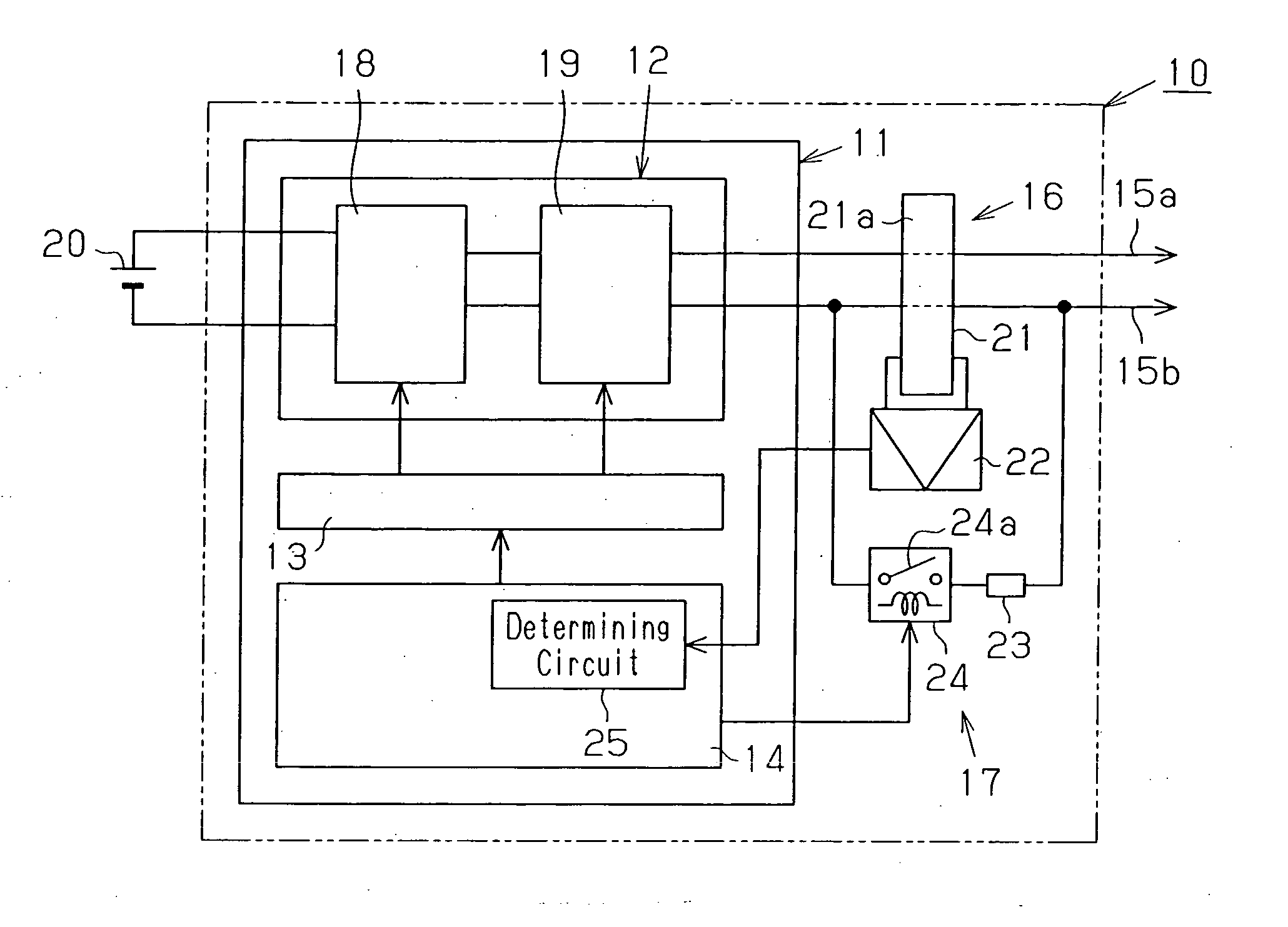
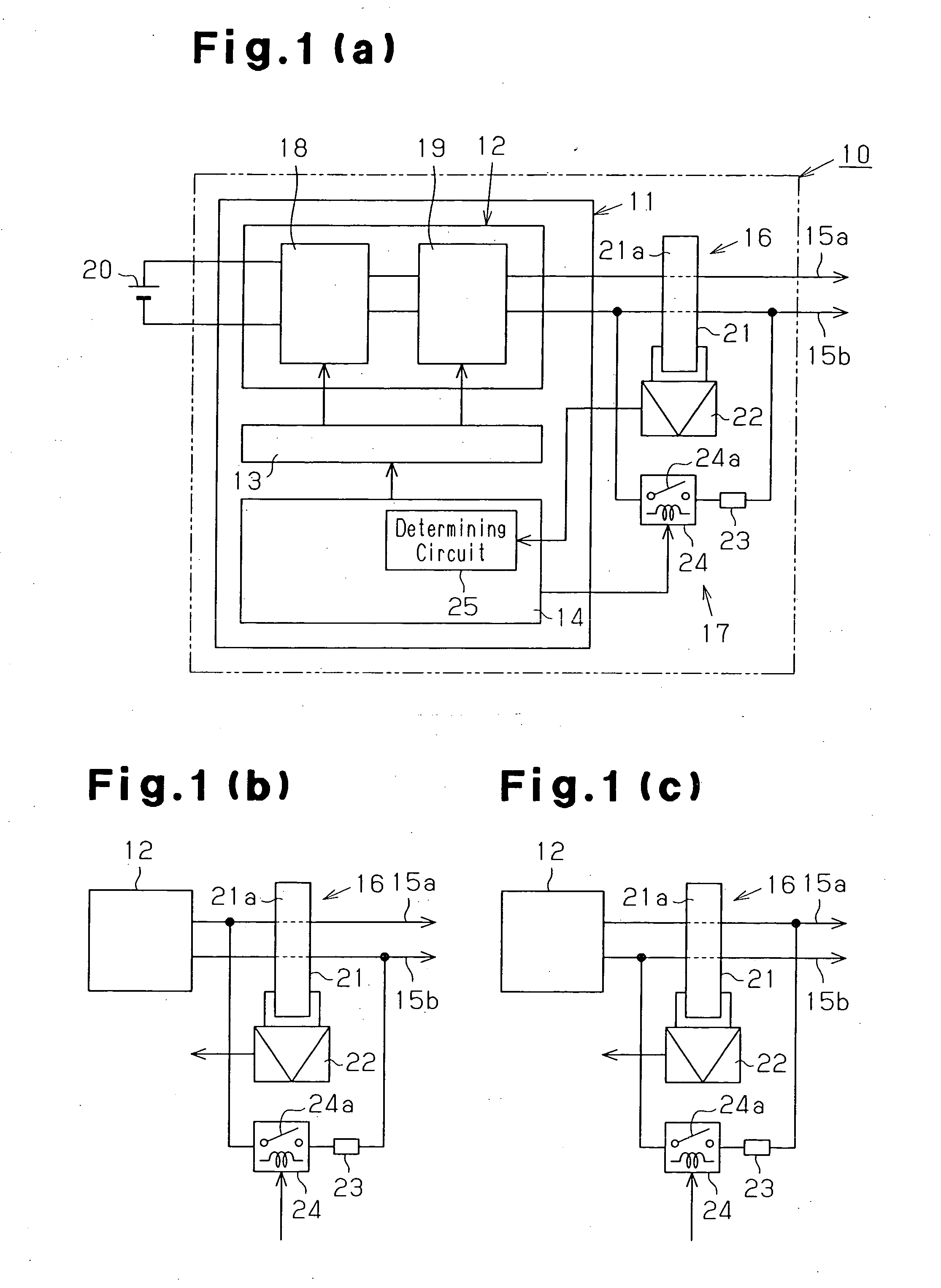
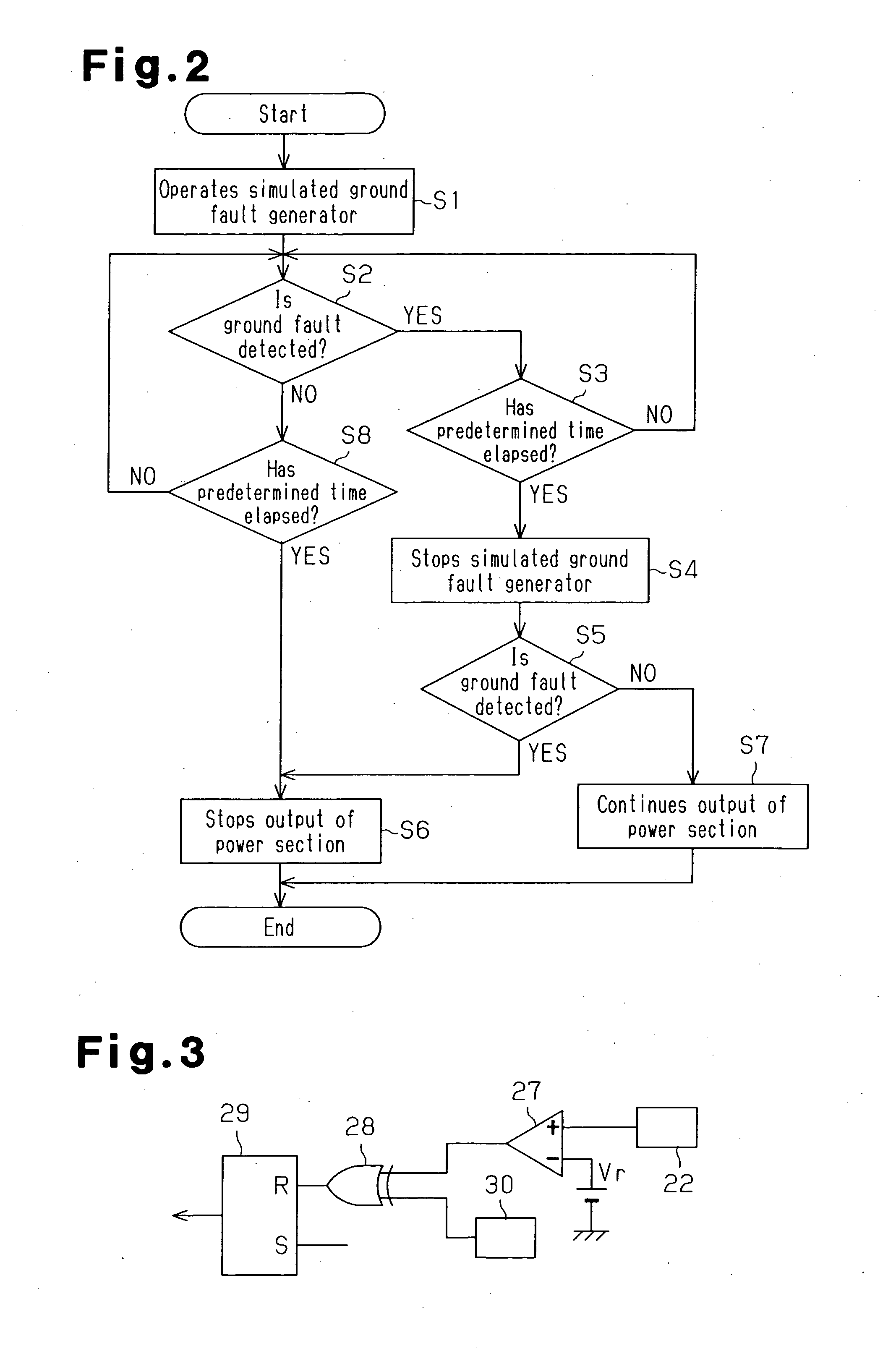
[0020] An inverter apparatus 10 for vehicles according to one embodiment of the present invention will now be described with reference to FIGS. 1(a) and 2. The inverter apparatus 10 converts a DC output of a battery 20 to an AC output. FIG. 1(a) is a schematic diagram of a power converter apparatus, which is the inverter apparatus 10 in this embodiment. FIG. 2 is a flowchart explaining operations performed when a ground fault is detected.

[0021] As shown in FIG. 1(a), an inverter section 11, which forms part of the inverter apparatus 10, includes a power section 12, a drive circuit 13, and a control section 14 in this embodiment. The output lines 15a and 15b are connected to the power section 12. Current from the power section 12 flows from the output line 15a to the output line 15b or in the reverse direction in a reciprocating manner. The inverter apparatus 10 also includes a ground fault detector 16, which detects a ground fault in the output lines 15a and 15b, and a simulated gr...


PUM


Abstract

A power converter apparatus converts electricity supplied from a power source into a different form and outputs the electricity to an output line. The apparatus includes a ground-fault detector and a simulated ground fault generator. When the ground fault detecting signal is output within an predetermined time and the output of the ground fault detecting signal is stopped as the simulated ground fault generator stops operating, a control section causes the power section to continue outputting electricity. When the signal is not output within the predetermined time or when the output of the signal is not stopped as the generator stops operating, the control section stops the power section. Therefore, the apparatus detects abnormality in the ground fault detector and continues supplying electricity without interruption when the detector is in a normal state.

Description

BACKGROUND OF THE INVENTION [0001] The present invention relates to a power converter apparatus and a method for controlling the apparatus, and more specifically to a power converter apparatus equipped with ground-fault detector. [0002] A typical household outlet having a ground-fault protection function includes a circuit configuration as shown in FIG. 5. An outlet 31 having a ground-fault protection function incorporates a ground-fault circuit interrupter 36. The ground-fault circuit interrupter 36 includes a sensor 32, which is so called zero phase-sequence current transformer (ZCT), an amplifier 33, which amplifies the detected voltage of the sensor 32, and a trip coil 35 for opening breaker contacts 34. The outlet 31 includes a ground-fault circuit 39, in which resistor 37 and a push button switch 38 are connected in series to intentionally cause a simulated ground-fault. When the push button switch 38 is pressed, the outlet 31 is in a state that is the same as when a ground-fa...

Claims


Application Information

Patent Timeline
Patent Type & Authority Applications(United States)
IPC IPC(8): G01R31/02H02H3/00H02H3/04H02H3/05H02H3/16H02H3/33
CPCH02H3/335H02H3/00H02H3/04
Inventor ASANO, HIROAKI
Owner TOYOTA IND CORP
Why Eureka
Try Eureka