Image processing apparatus and its method, program and storage medium

a technology of image processing and program storage, applied in the field of image processing apparatus, can solve the problems of ineffective noise removal, large increase in computation cost required for the process, and disturbance diagnosis

Inactive Publication Date: 2005-02-17
CANON KK
View PDF15 Cites 25 Cited by
  • Summary
  • Abstract
  • Description
  • Claims
  • Application Information

AI Technical Summary

Problems solved by technology

But an image sensed with a small X-ray dose contains many quantization noise components, which disturb diagnosis.
In a filter process for removing noise by extracting high-frequency components using a smoothed image, since a single frequency band is used, noise removal cannot be effectively made if noise components are distributed to a broad frequency band.
However, computation cost required for the process increases considerably.
In order to maintain optimal freque

Method used


Image

  • Image processing apparatus and its method, program and storage medium
  • Image processing apparatus and its method, program and storage medium
  • Image processing apparatus and its method, program and storage medium

Examples


first embodiment

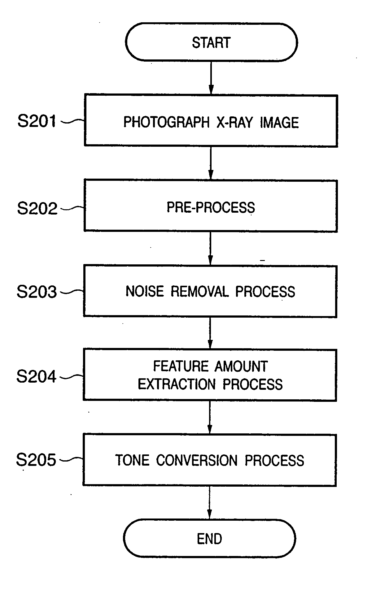
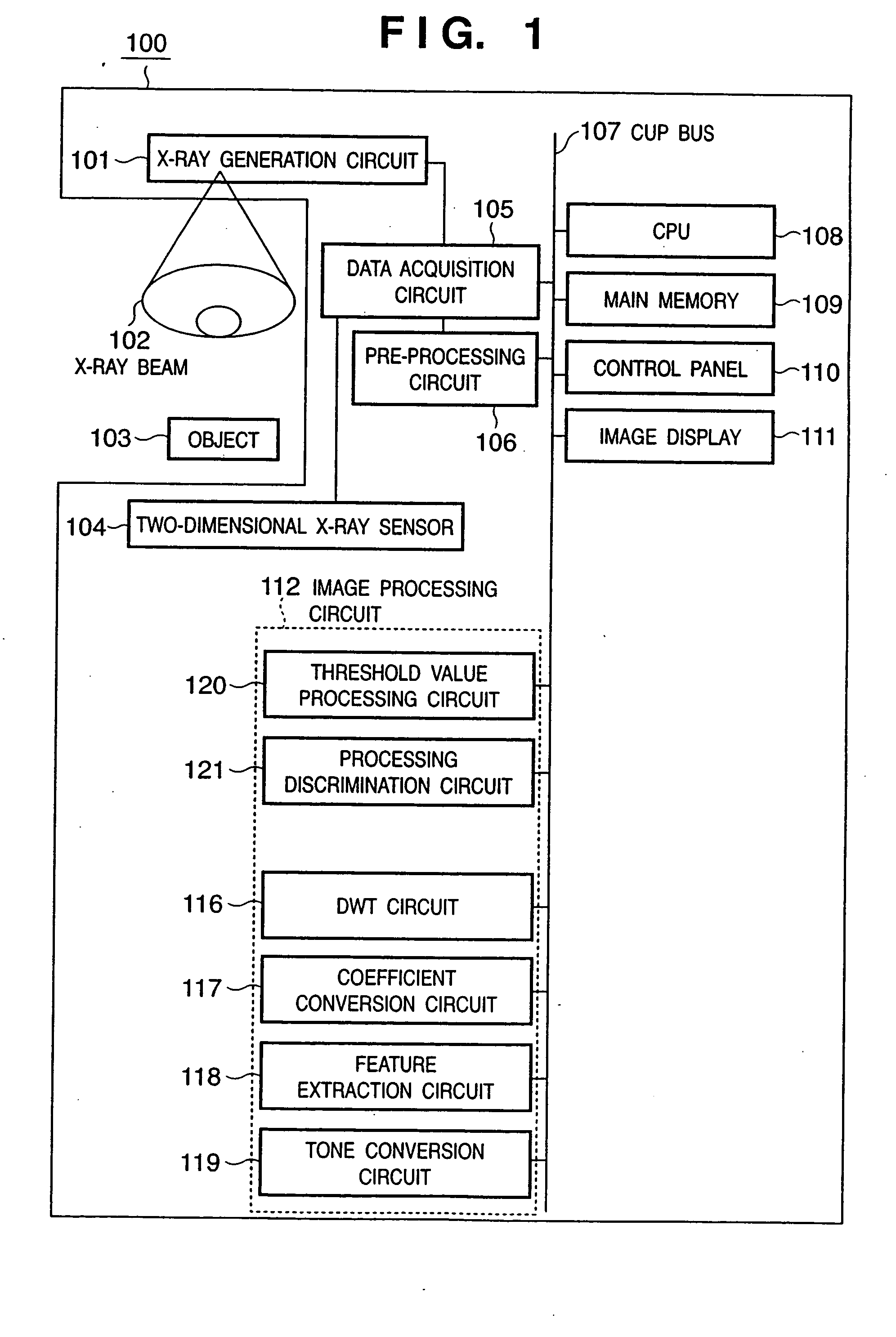
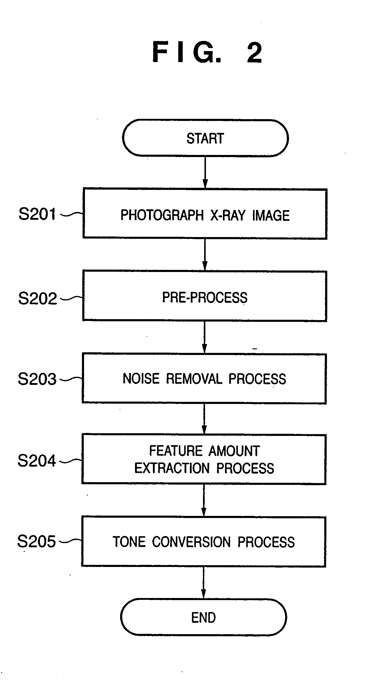
FIG. 1 shows the basic arrangement of an X-ray photographing apparatus 100 of this embodiment, and an object to be photographed using X-rays. An X-ray photographing apparatus 100 has a function of photographing an image of an object using X-rays, and removing noise from the photographed image, and comprises a pre-processing circuit 106, CPU 108, main memory 109, control panel 110, image display 111, and image processing circuit 112. Note that the image processing circuit 112 comprises a discrete wavelet transformation (DWT) circuit 116, coefficient conversion circuit 117, feature extraction circuit 118, tone conversion circuit 119, threshold value processing circuit 120, and processing discrimination circuit 121, which exchange data via a CPU bus 107.

The X-ray photographing apparatus 100 comprises a data acquisition circuit 105 connected to the pre-processing circuit 106, and a two-dimensional X-ray sensor 104 and X-ray generation circuit 101, which are connected to the data acqui...

second embodiment

In steps S302a to S304 of the first embodiment, the threshold value processes for determining the pixels to be processed in step S305 are done. However, the present invention is not limited to such specific processes. In this embodiment, three subbands are compared, and the pixels to be processed in step S305 are determined according to a pattern of the comparison results. That is, by exploiting the fact that more random noise components appear in the subband HH, the processes in steps S302a to S304 may be modified as:

if ((HL(x,y)<HH(x,y)) AND (LH(x,y)<HH(x,y))

then binary image HL(x,y) binary image LH(x,y)=binary image HH(x,y)=1;

else binary image HL(x,y)=binary image LH(x,y)=binary image HH(x,y)=0;

By combining the threshold value processes and comparison, the processes in steps S302a to S304 may be modified as follows to achieve the same object:

if (−THHH<HH(x,y)<THHH) then binary image HH(x,y)=1; else binary image HH(x,y)=0;

if ((HL(x,y)<HH(x,y...


PUM


Abstract

An object of this invention is to efficiently attain noise removal. In order to achieve the object, the discrete wavelet transforms of an input image are computed to output wavelet coefficients of respective subbands (S301). Appropriate threshold values are respectively set for subbands HL, LH, and HH indicating high-frequency components (S302a, S302b, S302c). The wavelet coefficients of the subbands HL, LH, and HH then undergo threshold value processes using the set threshold values for the respective subbands (S303a, S303b, S303c). Pixels to be processed in a coefficient conversion process are determined based on the threshold value processing results of the respective subbands (S304). The wavelet coefficients of the respective subbands corresponding to the pixels to be processed determined in step S304 undergo coefficient conversion (S305), and the converted transformation coefficients undergo inverse discrete wavelet transformation, thus reconstructing and outputting a noise-removed image (S306).

Description

FIELD OF THE INVENTION The present invention relates to an image processing apparatus for changing an image and, more particularly, changing transformation coefficients upon frequency transformation, its method, a program, and a storage medium. BACKGROUND OF THE INVENTION With the recent advance of digital technologies, a radiation image is converted into a digital image signal, and that digital image signal undergoes an image process, thus displaying the processed signal on, e.g., a CRT or printing it out. Upon photographing a radiation image, the X-ray dose is preferably as small as possible in consideration of the influences on a patient. But an image sensed with a small X-ray dose contains many quantization noise components, which disturb diagnosis. For this reason, processes for removing such noise have been conventionally examined. For example, a noise removal process using a simple median filter, a method of removing noise by extracting high-frequency components using a sm...

Claims


Application Information

Patent Timeline
IPC IPC(8): A61B6/00G06T5/00G06T5/10H03M7/30H04N1/409H04N5/21H04N7/18
CPCG06T5/10G06T5/002G06T2207/30004G06T2207/20064G06T2207/10116
Inventor MATSUURA, TOMOHIKO
Owner CANON KK
Why Eureka
Try Eureka