Fiber optic rotary joint and associated alignment method

a technology of fiber optic rotary joints and alignment methods, which is applied in the direction of optics, fibre mechanical structures, instruments, etc., can solve the problems of affecting the effective focal distance of collimation lenses, affecting the optical properties of fluids that fill internal cavities, and affecting the efficiency of optical signals coupled, so as to facilitate the orientation of optical fibers

Active Publication Date: 2005-02-17
MOOG INC
View PDF11 Cites 92 Cited by
  • Summary
  • Abstract
  • Description
  • Claims
  • Application Information

AI Technical Summary

Benefits of technology

[0012] An improved fiber optic rotary joint and its attendant components are therefore provided that can maintain the alignment of first and second bundles of optical fibers as the optical properties of a fluid that fills the internal cavity of the fiber optic rotary joint vary. As such, the fiber optic rotary joint can be utilized in sub-sea applications in which the temperature and / or pressure to which the fiber optic rotary joint is exposed fluctuates which causes the density and, in turn, the optical properties of the fluid that fills the internal cavity of the fiber optic rotary joint to vary. According to another aspect of the present invention, a method of aligning an optical collimation array is provided that facilitates the orientation of the optical fibers to be parallel to the longitudinal axis of the outer sleeve in which the optical fibers are disposed. In this aspect of the invention, the method permits the orientation of the optical fibers to be readily adjusted and then affixed in position such that the optical fibers maintain the desired orientation during subsequent usage.
[0014] Each interface optical element includes an optically flat surface adapted to contact the fluid that fills the internal cavity. The interface optical element is also adapted to permit optical signals that are oriented normal to the optically flat surface to be transmitted between the fluid and the interface optical element. Since the optical signals enter and exit the interface optical element in a direction that is normal to the optically flat surface of the interface optical element, the optical signals are not refracted and, as such, variations in the optical properties, including the index of refraction, of the fluid that fills the internal cavity of the fiber optic rotary joint do not affect the propagation of the optical signals. As such, the alignment of the first and second bundles of optical fibers is thereby maintained by the fiber optic rotary joint of the present invention as the optical properties of the fluid vary, such as in response to changes in the temperature and / or pressure to which the fiber optic rotary joint is exposed.
[0016] In this aspect of the present invention, one interface optical element is disposed proximate a respective end surface of the reversion prism. The interface optical element is positioned such that the optically flat surface is orthogonal to the longitudinal axis. Thus, the optical signals that enter and exit the reversion prism assembly are advantageously normal to the optically flat surface of the interface optical element, thereby permitting the optical properties, including the index of refraction, of the fluid to vary without adversely affecting the propagation of the optical signals therethrough. Typically, the reversion prism assembly also includes a second interface optical element disposed proximate the opposite end surface of the reversion prism such that the optical signals entering and exiting the reversion prism assembly from either end are immune to variations in the optical properties of the fluid. While the reversion prism and the interface optical element(s) may be formed of various materials, the reversion prism generally has an index of refraction that is greater than the index of refraction of the interface optical element.
[0019] The optical collimation assembly may also include a sleeve in which the collimating lens and the interface optical element are disposed. The sleeve generally opens into a housing that is at least partially filled with the fluid such that the interface optical element is exposed to the fluid. Since the optically flat surface of the interface optical element is orthogonal to the collimation optical axis, however, the optical signals enter and exit the interface optical element at an orientation that is normal to the optically flat surface such that variations in the optical properties, including the index of refraction, of the fluid do not adversely affect the propagation of the optical signals therethrough. The optical collimation assembly may further include one or more index matching elements disposed within the sleeve, such as between an end portion of the optical fiber and the collimating lens and / or between the collimating lens and the interface optical element. The index matching elements prevent the fluid from residing in the optical path within the optical collimation assembly, such that variations in optical properties, including index of refraction, of the fluid do not adversely affect the effective focal length for the collimating lens. Additionally, the index matching elements are included so as to reduce undesirable back reflections within the optical collimation assembly.
[0023] According to this aspect of the present invention, an optical collimation array including a plurality of optical fibers may be efficiently aligned such that each collimation assembly including each optical fiber is positioned to be parallel to the physical axis of the optical collimation array. As such, optical signals transmitted and received by the optical collimation array can be more reliably and maintainably aligned with another optical collimation array, such as within a fiber optic rotary joint or the like.
[0024] Accordingly, an improved fiber optic rotary joint is provided according to one embodiment of the present invention that maintains the alignment of first and second bundles of optical fibers as the optical properties, including the index of refraction, of the fluid that fills the fiber optic rotary joint varies in response to temperature and / or pressure changes. In this regard, a reversion prism assembly and / or an optical collimation assembly may be provided in which interface optical element(s) are disposed proximate the reversion prism and the collimating lens, respectively, in order to provide an optically flat surface through which signals enter and exit with an orthogonal orientation so as not to be refracted by the fluid disposed within the internal cavity of a fiber optic rotary joint. According to another aspect of the present invention, an improved method of aligning an optical collimation array such that the plurality of collimation assemblies including the plurality of optical fibers are commonly oriented to be parallel to the physical axis of the optical collimation array, thereby also improving the alignment of the bundles of optical fibers optically interconnected by a fiber optic rotary joint.

Problems solved by technology

Unfortunately, the optical properties of the fluid that fills the internal cavity of a fiber optic rotary joint vary significantly with changes in temperature and / or pressure due to corresponding changes in the density of the fluid.
Additionally, variations in the index of refraction of the fluid that fills the internal cavity of a fiber optic rotary joint alters the effective focal distance of the collimation lens.
Accordingly, optical signals will not be coupled as efficiently, if at all, between the first and second bundles of optical fibers, thereby adversely affecting the optical performance of the fiber optic rotary joint.
In this regard, even a slight misalignment of the optical fibers will increase the insertion loss and, in some instances, render the fiber optic rotary joint unacceptable for at least some applications.
Such outer sleeves or bearings are therefore rarely, if ever, an off-the-shelf part and must be specifically manufactured to exacting tolerances, thereby increasing the overall cost of the fiber optic rotary joint.
As such, the optical signals emitted by the bundle of optical fibers that are somewhat twisted may not be properly aligned with respective optical fibers of the other bundle of optical fibers, thereby reducing the efficiency with which optical signals are transmitted therebetween.
As will be recognized, this individual alignment can be quite time consuming.
Unfortunately, the epoxy may cause the optical fibers to become slightly misaligned as the epoxy cures, thereby again disadvantageously increasing the insertion loss.

Method used


Image

  • Fiber optic rotary joint and associated alignment method
  • Fiber optic rotary joint and associated alignment method
  • Fiber optic rotary joint and associated alignment method

Examples


Embodiment Construction

[0031] The present inventions now will be described more fully hereinafter with reference to the accompanying drawings, in which some, but not all embodiments of the invention are shown. Indeed, these inventions may be embodied in many different forms and should not be construed as limited to the embodiments set forth herein; rather, these embodiments are provided so that this disclosure will satisfy applicable legal requirements. Like numbers refer to like elements throughout.

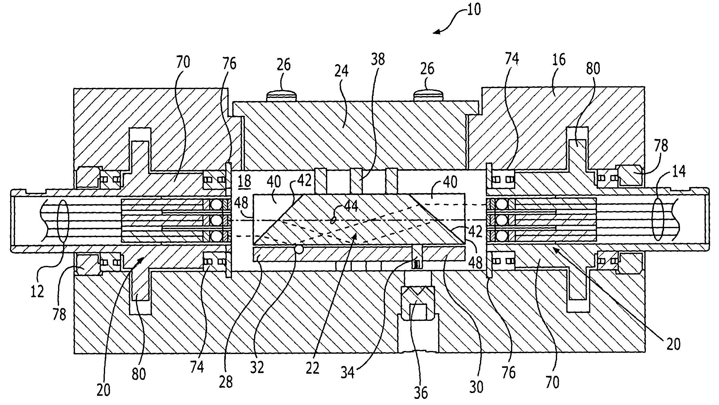
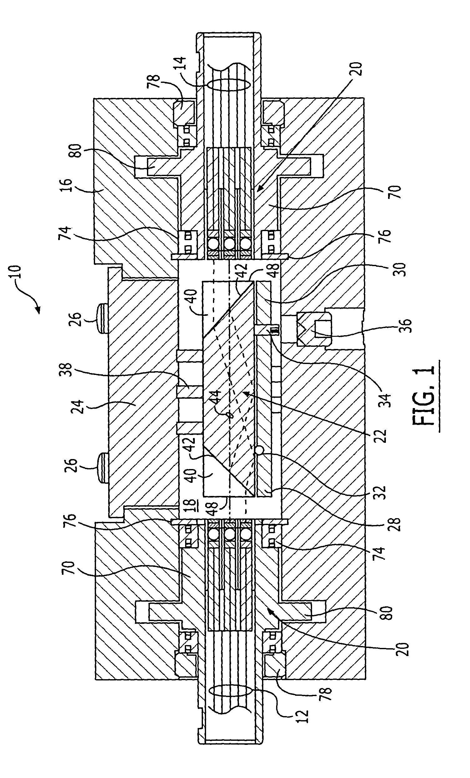
[0032] As shown in FIG. 1, a fiber optic rotary joint 10 according to one aspect of the present invention is depicted. The fiber optic rotary joint may be employed in a variety of applications, including sub-sea as well as other applications. As described below, the fiber optic rotary joint is designed to optically interconnect first and second bundles 12,14 of optical fibers while permitting at least one of the bundles to rotate relative to the other bundle. While one bundle is generally held stationary and ...


PUM


Abstract

A fiber optic rotary joint is provided that is unaffected by variations in the optical properties of a fluid that fills its internal cavity. The rotary joint includes a housing defining the internal cavity, first and second optical collimation arrays on opposite sides of the internal cavity, and a reversion prism between the optical collimation arrays. Further, the rotary joint includes an interface optical element proximate at least one of the first and second optical collimation arrays and the reversion prism. Each interface optical element includes an optically flat surface adapted to contact the fluid such that optical signals that are oriented normal to the optically flat surface can be transmitted without refraction, thereby rendering the optical signals immune to variations in the fluid's optical properties. A reversion prism assembly, an optical collimation assembly and a method of aligning an optical collimation array utilizing alignment pins are also provided.

Description

CROSS-REFERENCE TO RELATED APPLICATIONS [0001] This application claims the benefit of U.S. Provisional Application No. 60 / 494,445, filed Aug. 12, 2003, the contents of which are incorporated herein in their entirety.FEDERALLY SPONSORED RESEARCH OR DEVELOPMENT [0002] The research underlying this invention was supported at least in part with funds from U.S. Navy Contract No. N00024-00-C-4059. The United States Government may therefore have an interest in the subject matter of this invention.FIELD OF THE INVENTION [0003] The present invention relates generally to fiber optic rotary joints and associated alignment methods and, more particularly, to reversion prism assemblies, optical collimation assemblies and associated fiber optic rotary joints that include an interface optical element that is exposed to the fluid within the fiber optic rotary joint and that is designed to reduce, if not eliminate, the deleterious effects otherwise caused by changes in the index of refraction of the f...

Claims


Application Information

Patent Timeline
Patent Type & Authority Applications(United States)
IPC IPC(8): G02B6/36G02B6/44
CPCG02B6/4428G02B6/3604
Inventor OOSTERHUIS, MARTIN J.PERDUE, JERRY T.SUTPHIN, CARLTON W.
Owner MOOG INC
Why Eureka
Try Eureka