
Method, system and apparatus for media distribution and viewing verification

Inactive Publication Date: 2005-02-17
THINKING PICTURES
View PDF13 Cites 74 Cited by
  • Summary
  • Abstract
  • Description
  • Claims
  • Application Information

AI Technical Summary

Benefits of technology

[0013] It is another object of the present invention to provide tools to advertisers for use in ad generation. In one embodiment, the tools enable the ad generator to easily arrange sound, still image and moving image files into an ad and specify how the ad behaves when idle or interacting with a viewer. In another embodiment, the tools enable the ad generator to easily generate a plurality of ads that interact together on a plurality of display units. In one embodiment, the tool provides display unit lay-out information for all locations containing display units. In another embodiment, the tool provides a standard set of display unit lay-outs (e.g., two units in a row, five units in a row or a unit in the middle of each wall of a room). In one embodiment, the tool provides a virtual three dimensional viewing environment so that the ad generator can view how the interacting displays will appear. The viewing environment enables the ad generator to rotate the view 360 degrees to view all display units on walls and enables the ad generator to shift the view up or down to view displays placed higher or lower than eye level on walls as well as any displays placed on the ceiling or floor.

Problems solved by technology

However, since the posters are static, only a limited number of items can be displayed at one given time.
Additionally, the posters are limited in their ability to attract viewers' attention and there is no method of verifying for an advertiser that a poster was viewed by anyone, and to quantify the number of viewers in a particular time period

Method used


Image

  • Method, system and apparatus for media distribution and viewing verification
  • Method, system and apparatus for media distribution and viewing verification
  • Method, system and apparatus for media distribution and viewing verification

Examples


Embodiment Construction

[0028] The invention is a method, system and apparatus for media distribution and viewing verification. In the following description, numerous specific details are set forth to provide a more thorough description of embodiments of the invention. It is apparent to one skilled in the art, however, that the invention may be practiced without these specific details. In other instances, well known features have not been described in detail so as not to obscure the invention.

[0029] Media Distribution and Viewing Verification Architecture

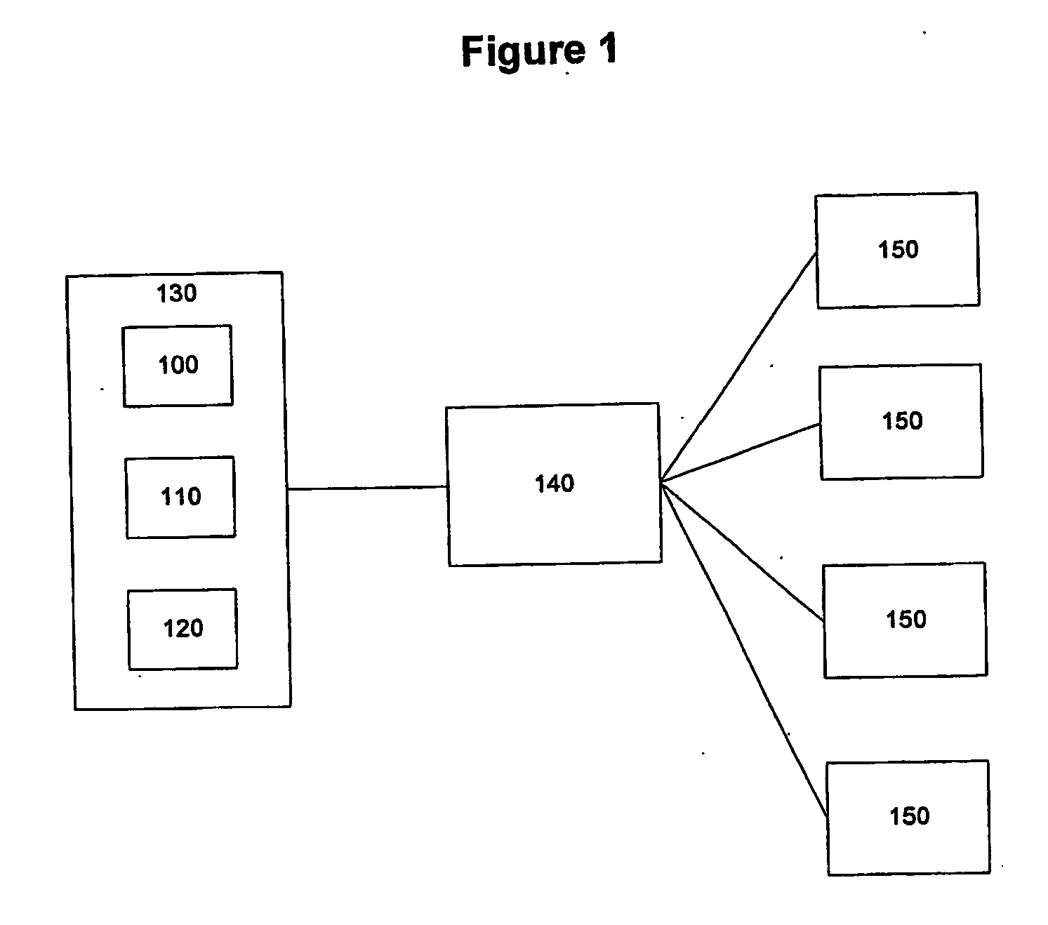
[0030] In one embodiment, media content is stored in a database. Media content from the database is arranged into a schedule and displayed on a display unit. FIG. 1 illustrates an architecture for a media distribution and viewing verification architecture in accordance with one embodiment of the present invention. Media content 100, schedule information 110 and viewer information 120 are stored in one or more central databases 130. The central database c...


PUM


Abstract

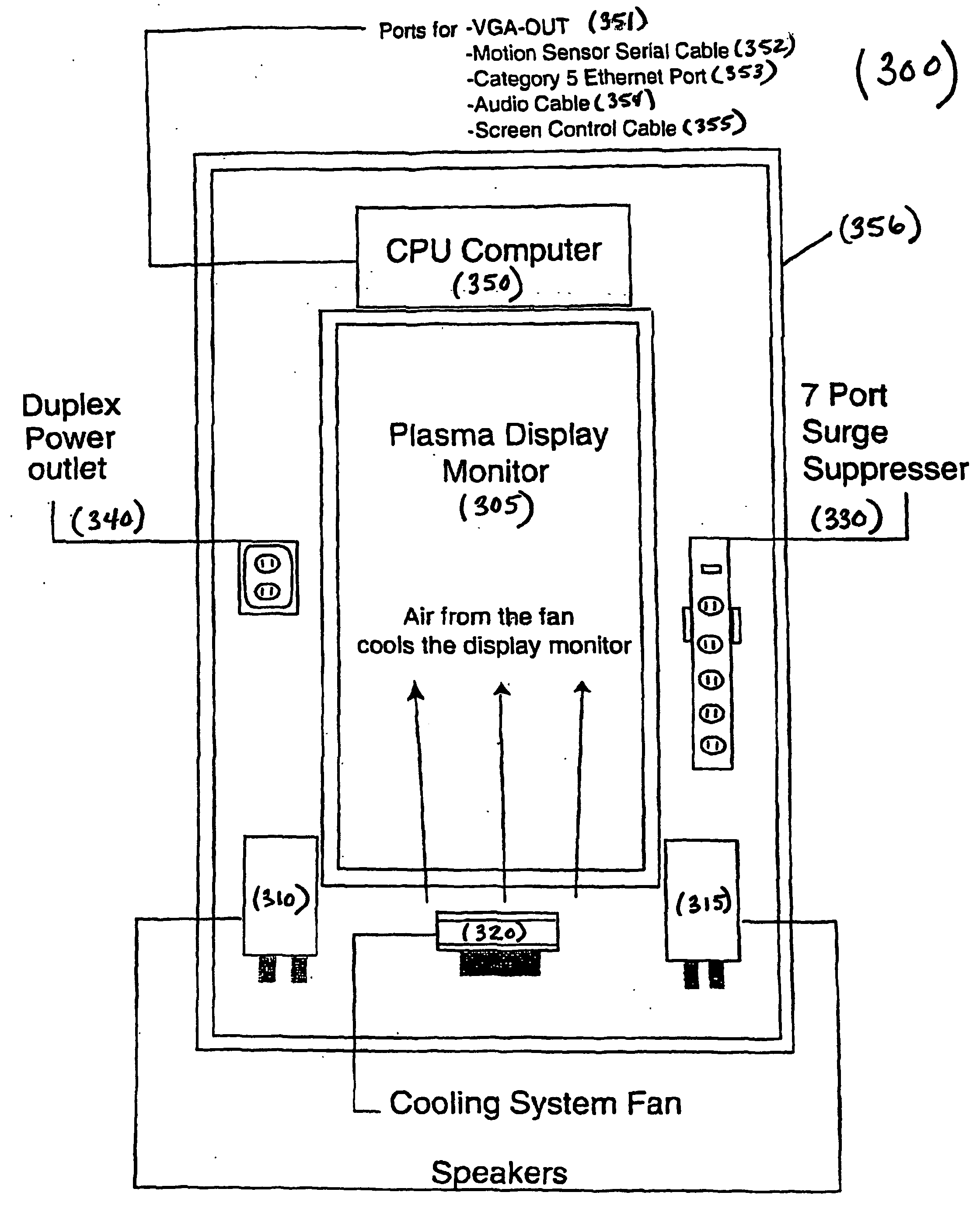
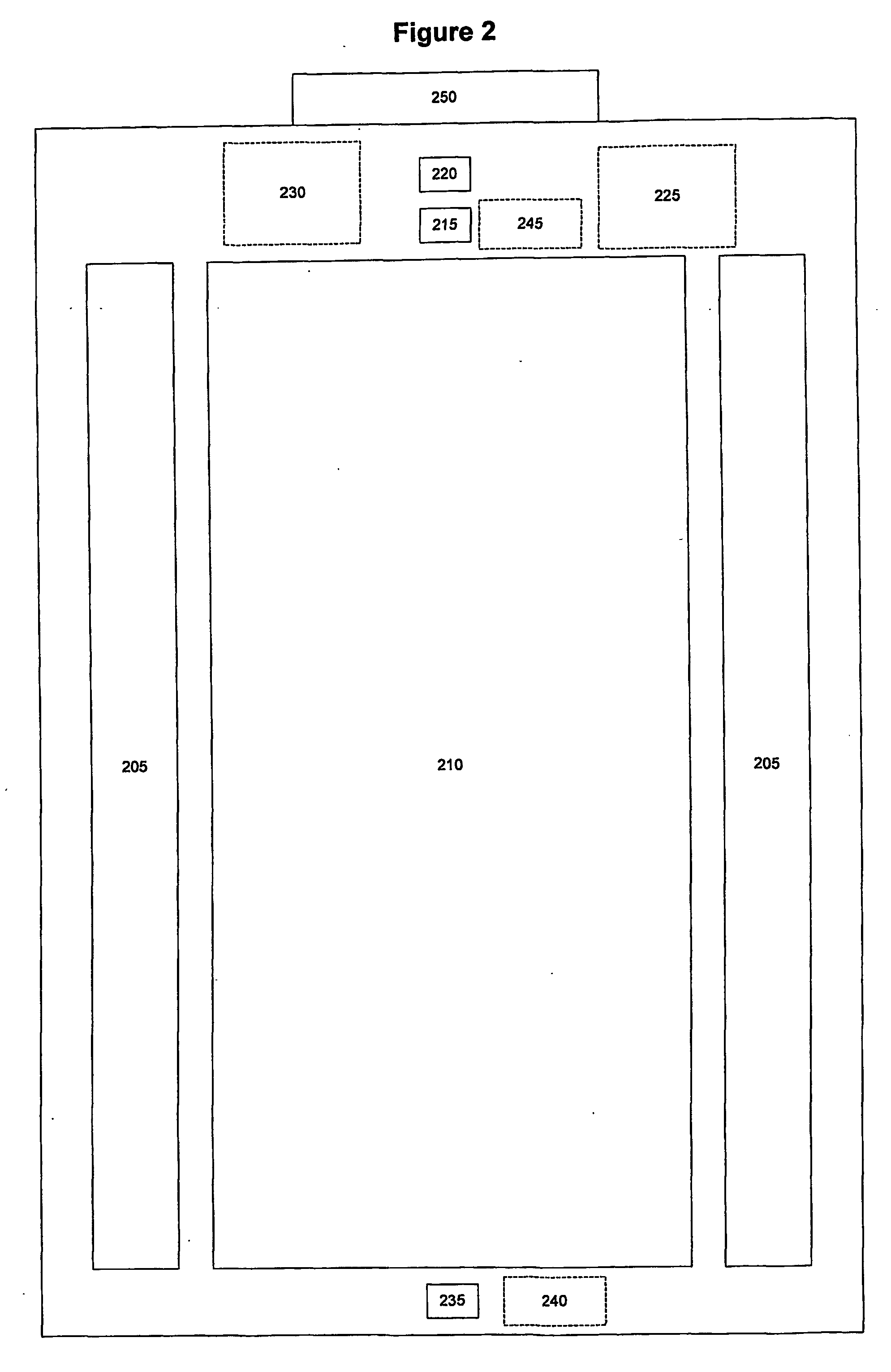
The present invention is directed to a method, system and apparatus for media distribution and / or viewing verification. In one embodiment of the present invention, media content is stored in a database. Media content from the database is arranged into a schedule and displayed on a display unit. In one embodiment, the display unit comprises a flat panel display with stereo speakers placed in a wall in approximately the same space as is occupied by a traditional movie poster display case. In one embodiment, the display unit is retro-fitted to a traditional movie poster display case. In one embodiment, a display unit has a sensor unit. One embodiment has motion sensors used in determining whether the display is being viewed. Another embodiment has video sensors used in determining whether the display is being viewed and / or determining the number of viewers. Another embodiment has a card reader sensor used to gather information about a viewer. Another embodiment has a touch-screen monitor used to gather information from a viewer.

Description

RELATED APPLICATION INFORMATION [0001] This application claims the benefit of U.S. Provisional Patent Application Ser. No. 60 / 343,342, filed Dec. 21, 2001, entitled, “Method, System and Apparatus for Media Distribution and Viewing Verification,” the disclosure of which is hereby incorporated by reference in its entirely.FIELD OF THE INVENTION [0002] The present invention relates to the field of media distribution, and in particular to a method, system and apparatus for media distribution and viewing verification. BACKGROUND OF INVENTION [0003] Posters of still images are frequently used to advertise services and products. For example, movie theaters often display posters of upcoming new releases. However, since the posters are static, only a limited number of items can be displayed at one given time. Additionally, the posters are limited in their ability to attract viewers' attention and there is no method of verifying for an advertiser that a poster was viewed by anyone, and to qua...

Claims


Application Information

Patent Timeline
IPC IPC(8): G06Q30/00G06F13/00G06T1/00G09F19/00H04H1/00H04H60/45H04H60/46H04H60/52H04N7/16H04N7/173
CPCH04H60/45H04N21/8153H04H60/52H04N7/162H04N7/163H04N7/17318H04N21/25883H04N21/4122H04N21/41415H04N21/42201H04N21/4223H04N21/441H04N21/44218H04N21/4784H04N21/812H04H60/46
Inventor FITCH, STEPHAN JSEGALOWITZ, DAVID S
Owner THINKING PICTURES
Learn More