Monitoring printer via network

a network and printer technology, applied in the direction of digital output to print units, instruments, data processing applications, etc., can solve the problem of discrepancy between the estimated consumption amount and the actual consumption amount of an expendable, and achieve the effect of quick calculation of usage charges and improved measurement accuracy of consumption of an expendabl

Inactive Publication Date: 2005-02-17
SEIKO EPSON CORP
View PDF7 Cites 27 Cited by
  • Summary
  • Abstract
  • Description
  • Claims
  • Application Information

AI Technical Summary

Benefits of technology

[0013] The predetermined information provided by the notification enables “another network-connected device” to quickly perform calculations of usage charges, replenish expendables, and so on.
[0014] According to this first a

Problems solved by technology

However, depending on the service environment of the printer, there may be discrepanc

Method used


Image

  • Monitoring printer via network
  • Monitoring printer via network
  • Monitoring printer via network

Examples


embodiment 1

[0046] A. Embodiment 1

[0047] A1: System Overview

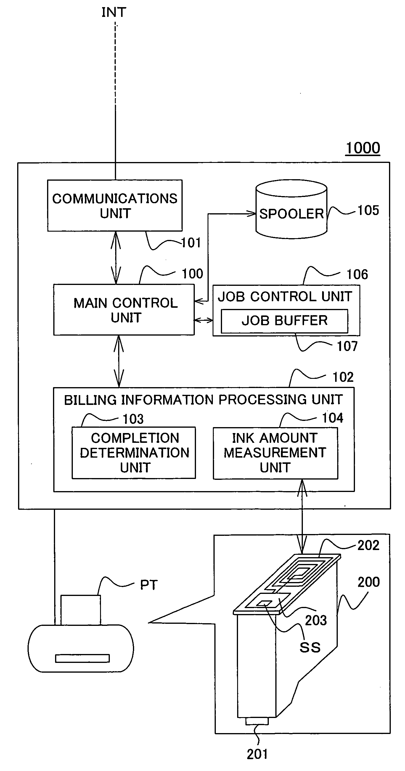
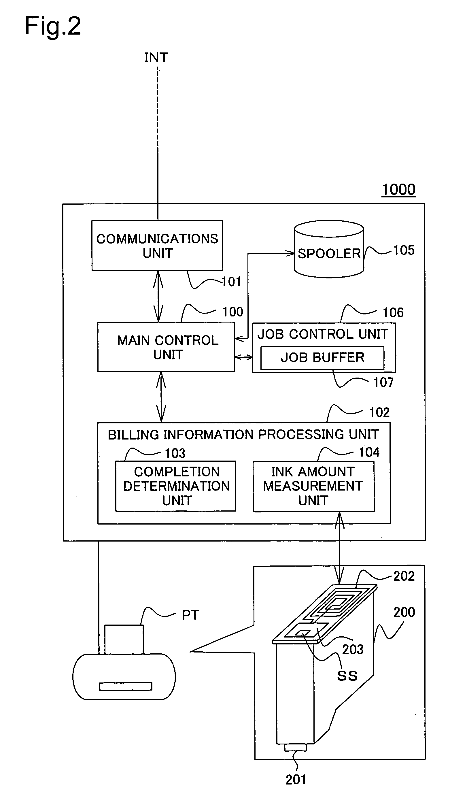
[0048] A2: Internal Arrangement

[0049] A3: Billing Information Notification Process

[0050] A4: Sheet Count Sensing Process

[0051] A5: Ink Amount Measuring Process

embodiment 2

[0052] B. Embodiment 2

[0053] B1: Information Amount Sensing Process [0054] C. Embodiment 3

[0055] C1: Charge Calculation Process

[0056] D. Variations

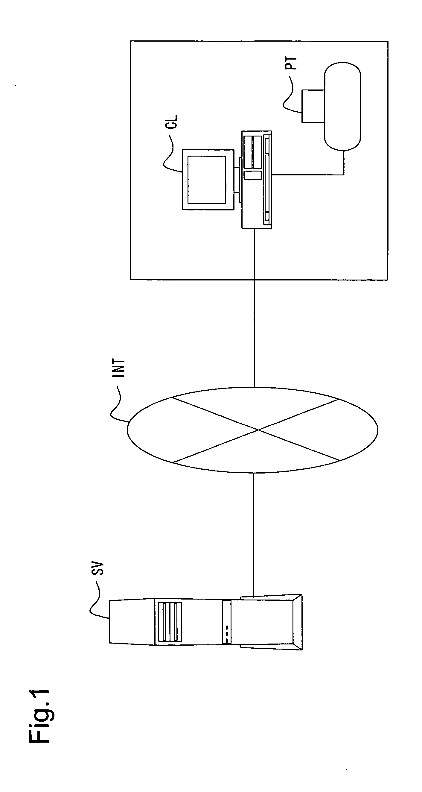
[0057] A1: System Overview

[0058]FIG. 1 is a simplified illustration of a monitoring system by way of a first embodiment. As shown in the drawing, an ink jet printer PT has a local connection to a client computer CL; the client computer CL connected to a central server SV (hereinafter “server SV”) via the Internet INT. A monitoring system is set up for the client computer CL. In this embodiment, the user is charged according to amounts of expendables consumed by printer PT.

[0059] Client computer CL queues a print job onto the spooler corresponding to the printer PT. When the queued print job has been arranged in print order, it is sent to the printer PT, which commences printing. Client computer CL performs monitoring of completion of printing of the print job, measurement of the amount of ink used by printer PT, and acquisition of th...

embodiment 3

[0095] C. Embodiment 3

[0096] C1: Charge Calculation Process

[0097] In Embodiment 1 and Embodiment 2, billing calculations are performed by the server SV, on the basis of information provided by notification from the monitoring system 1000. In Embodiment 3, billing calculations are performed by the monitoring system 1000, which then notifies the server SV of the calculated charges. The system overview in this embodiment is similar to that in Embodiment 1 and Embodiment 2. However, the billing information processing unit 102 performs the billing calculations on the basis of information received from the completion determination unit 103 and ink amount measurement unit 104.

[0098]FIG. 7 is flowchart of a charge calculation process in Embodiment 3. The client CL initiates the process at the point in time that a print job is issued. The processes of Step S201-Step S204 are similar to the process of Step S10-Step S13 of Embodiment 1, and need not be described here.

[0099] On the basis of ...


PUM


Abstract

Amounts of expendables consumed by a printer are sensed accurately. A job control unit 106 transfers a print job queued in job buffer 107 to a spooler 105, in page units. Spooler 105 sends the print job to a printer PT, as well as providing a completion determination unit 103 with notification of start of printing. Upon receiving notification of start of printing, the completion determination unit monitors the status of the printer PT and remaining data in the spooler 105, and in the event that printer PT status is “ready to print” and there is no remaining data in the spooler 105, decides that printing has completed, and counts the number of sheets of paper. An ink amount measurement unit 104, by means of predetermined correcting means, corrects the amount of ink consumed during printing, so as to approximate the amount of ink actually used in printing. A server SV is notified of the number of sheets of paper and the corrected amount of ink consumed, whereupon the server performs a billing process.

Description

TECHNICAL FIELD [0001] The present invention relates to a technique for monitoring a printer via a network, and more particularly to a technique for monitoring the status of expendable supplies for a printer, and / or service status of the printer. BACKGROUND ART [0002] To date, there has been proposed a business model in which a printer is loaned to a user, whose is then charged according to consumed amounts of expendable supplies such as ink and printer paper. In the context of such a business, it has also been proposed to remotely monitor consumption of expendables via a network. [0003] Exemplary methods for identifying amount of ink consumed include mathematical calculation, and monitoring with sensors. With the former approach, the amount of ink ejected in drops by the print head, and the amount of ink suctioned out during maintenance processes, are added up by a software application, to arrive at calculated ink consumption. For the latter, a method wherein two electrodes are pro...

Claims


Application Information

Patent Timeline
IPC IPC(8): G06F3/12B41J29/38
CPCG06F3/1219G06Q10/06G06F3/1285G06F3/1229
Inventor HANAOKA, MASAAKI
Owner SEIKO EPSON CORP
Why Eureka
Try Eureka