Flywheel energy storage systems

a technology of energy storage and flywheel, which is applied in the direction of electric storage system, mechanical energy handling, mechanical equipment, etc., can solve the problems of limited energy storage capacity of conventional flywheel materials, excessive bulky motor/generator and control typically used with flywheels, and limited potential competitiveness of flywheel energy storage systems. , to achieve the effect of minimizing the wear of solid-lubricant film, minimizing the orbiting restraint of balls or rollers, and sufficient biasing

Inactive Publication Date: 2005-02-24
KINETECH POWER CO LLC
View PDF4 Cites 66 Cited by
  • Summary
  • Abstract
  • Description
  • Claims
  • Application Information

AI Technical Summary

Benefits of technology

[0020] In another of its many aspects this invention provides for integration of such woven fabric composite flywheel rings and other types of flywheels as mentioned immediately above with space-vector, sine-wave-drive, digital signal processing-controlled, compact, sensorless-commutated, either longitudinal or transversal-flux, radial or axial gap motor / generators with or without permanent magnets, the latter of which are referred to as reluctance designs, in high-efficiency flywheel energy storage systems using solid-lubricated ball, roller and other bearing assemblies, together with permanent-magnet non-flux-penetrating thrust compensators requiring little or no conventional periodic re-lubrication or maintenance. In another of its many aspects the invention provides heat pipe-cooled bearings and motor rotors, fail-safe rapid energy dump systems, and lubrication facilitating geometries for ball, roller and sliding bearings, as well as vibration-decoupling mounting systems in high-speed super-critical flywheel energy storage systems, allowing the rotor to spin about its mass center thereby to minimize bearing loads during high-speed operation and thus increase system life, reliability and safety.
[0056] In the vibration-minimizing decoupling aspect of the invention there is further embraced a method for accelerating a rotating body through a critical frequency of rotation with the body having a second portion tending to separate from a first portion at body angular velocity below the critical frequency. The method includes permitting the second portion to move away from the first portion responsively to centrifugal force at rotational speed below the critical frequency thereby reducing effective mass of the rotating body and establishing a new critical frequency for the rotating body substantially shifted downwardly from the original critical frequency, the second portion is then preferably connected to the first portion only by a flexible element, thereby increasing the effective compliance of the bearing support of the rotating body. The method further embraces optionally maintaining a flexible couple between the first and second portions to facilitate substantially unitary rotation thereof at common velocity but with separate angular momenta. The method may further optionally include the step of permitting the second portion to self-bias itself radially inwardly to effectuate complemental contact between facing surfaces of the first and second portions when the body is at rest and at ambient temperature.

Problems solved by technology

However, despite recent improvements in fiber-reinforced composites, continuous-filament-wound ring designs, electronic controls, and bearing lubrication and vibration-control technology, flywheel energy systems have still been only potentially competitive with alternative energy storage devices such as chemical batteries and ultra-capacitors.
Conventional flywheel materials are limited in their energy storage capacity by their centrifugal burst strength at high rotating speeds.
Motor / generators and controls typically used with flywheels are too bulky and cannot run at the high speeds required for a compact flywheel energy storage system to fit the volume constraints of automotive and other vehicular applications.
Application of lower energy density flywheel energy storage systems for stationary utility load-leveling applications has not been successful due in part to lack of proven designs for low-cost continuous-filament ring materials.
However, known Hall-effect systems are complex, awkward and difficult to manufacture, install and align, limiting their use in high-speed machines where brushless characteristics are a distinct advantage.
In high-speed flywheel energy storage systems, conventional bearings do not have sufficient life in the vacuum environment required to minimize windage losses and composite flywheel ring overheating.
Even magnetic bearings, however, require auxiliary ball or roller bearings to support the rotor in the event either of an inadvertent loss of power to the magnetic bearings or high gyroscopic maneuvering or impact loads that exceed the load capability of the magnetic bearings.
Lubricating greases and the ultra-low volatility synthetic lubricating oils required in the high vacuum of such systems with low cost ball bearings do not have the additive response of synthetic hydrocarbons or conventional petroleum-based oils, so that they have unacceptably short boundary lubricating ability and bearing life.
In such known solid-lubricated bearing applications, sporadic catastrophic bearing failures occur.
Self-contained greased-for-life bearings have limited high-speed capabilities and require frequent re-lubrication.
Unfortunately, squeeze-film dampers have their own instabilities due to oil whirl and oil whip and often induce instabilities in such high speed machinery.
Additionally, squeeze-film damper design is an ill-defined art.
Furthermore, squeeze-film dampers do not provide high damping ratios.
Hence, high vibrational bearing loads and system instabilities often result when squeeze-film dampers are utilized.

Method used


Image

  • Flywheel energy storage systems
  • Flywheel energy storage systems
  • Flywheel energy storage systems

Examples


Embodiment Construction

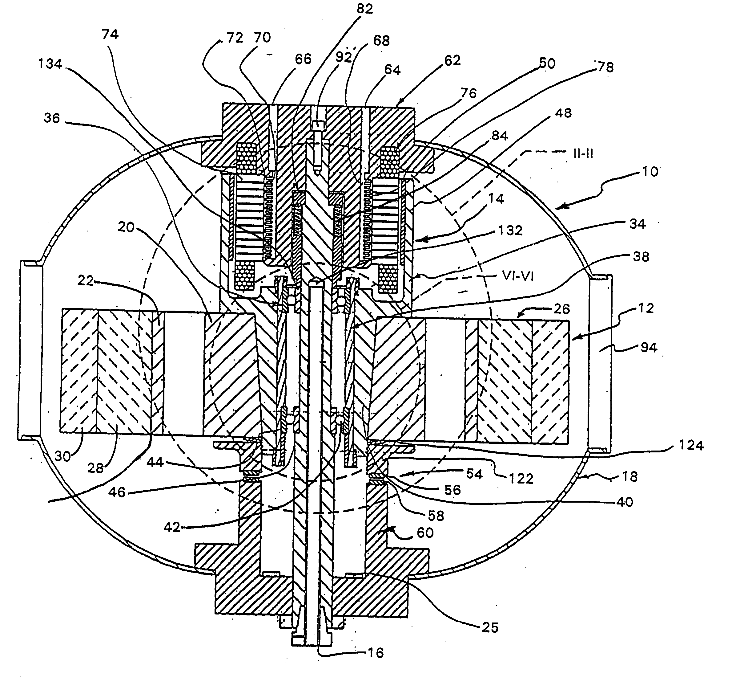
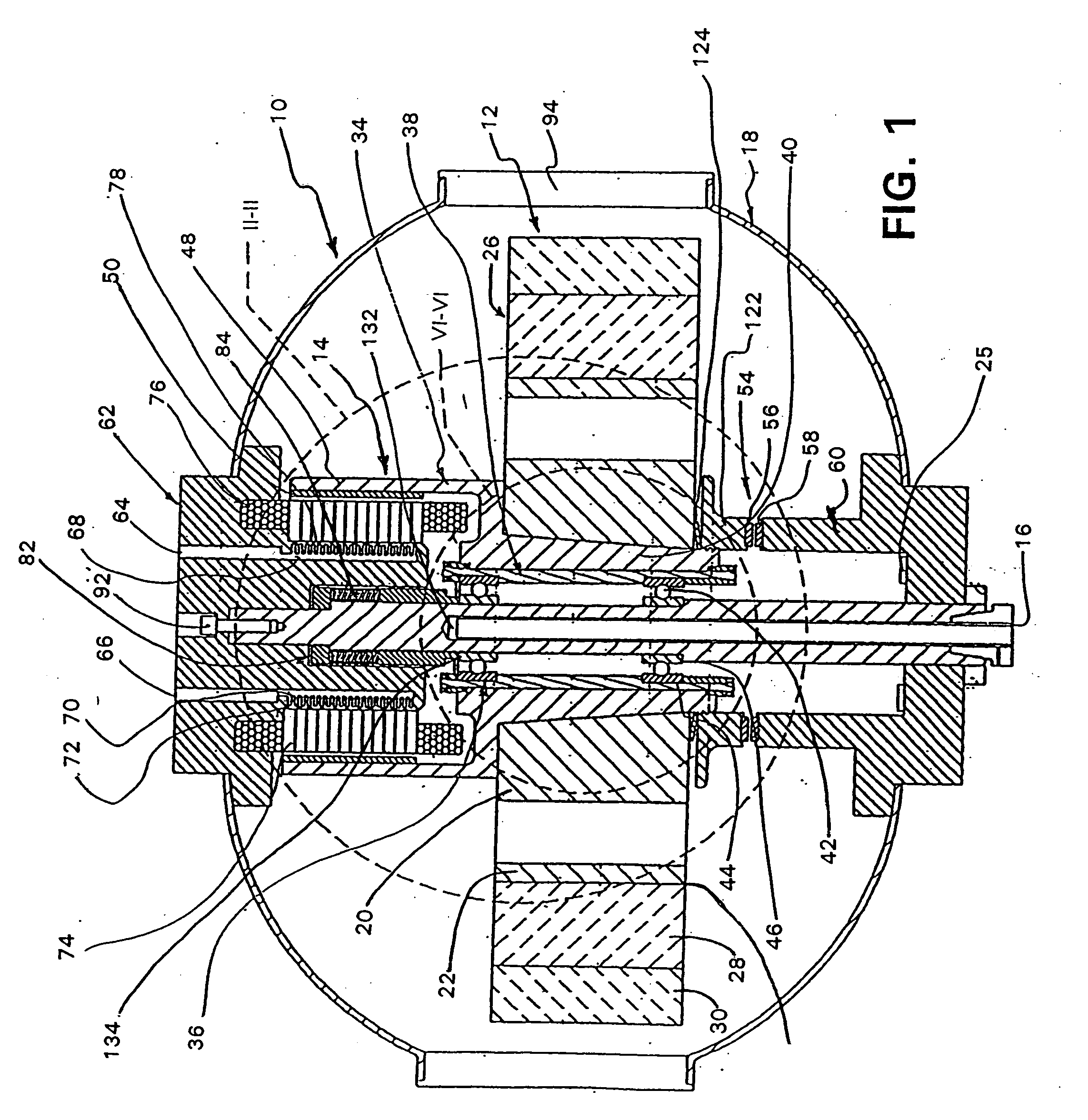
[0096] Referring to the drawings in general and to FIG. 1 in particular, a flywheel energy storage system manifesting aspects of the invention and representing a first preferred embodiment of the invention is illustrated generally in FIG. 1 and designated generally 10. Flywheel energy storage system 10 includes a flywheel which has been designated generally 12, a motor / generator which has been designated generally 14 and which provides means for selectably rotating flywheel 12 responsively to electrical power input to motor / generator 14 or for producing electrical power upon rotation of a rotor portion of motor / generator 14 by flywheel 12.

[0097] Flywheel energy storage system 10 further includes a shaft designated generally 16 which is stationary in the embodiment illustrated in FIG. 1 and about which flywheel 12 and the rotatable portion of motor / generator 14, referred to as the rotor, rotate.

[0098] Flywheel energy storage system 10 further preferably includes a vacuum enclosure ...


PUM


Abstract

A flywheel energy storage system (10) includes a vacuum enclosure (18) having a flywheel (12), motor / generator (14), and a shaft (16) enclosed within. The flywheel and motor / generator combination are designed to minimize bearing loads and thus increase system life, reliability and safety.

Description

INCORPORATION BY REFERENCE [0001] The disclosures of U.S. Pat. Nos. 5,486,052, 5,356,227 and 5,066,145 are hereby incorporated by reference.BACKGROUND OF THE INVENTION [0002] 1. Field of the Invention [0003] This invention relates to flywheel energy storage systems, to integration of advanced-technology fiber-reinforced composite thick-ring flywheels, low-cost continuous-filament unbonded steel wire and other filament flywheels and mounting hub designs, with ultra-compact and in some cases low-cost conventional motor / generators and digital signal processing-based electronic controller systems, fail-safe vacuum enclosures, emergency energy-dump and containment systems and ball, roller and sleeve bearings having solid lubricants, all of which can operate reliably for many years without maintenance. This invention also relates to the use of the gyroscopic moment generated by such flywheel for orienting the load of a suspended device in the manner described in U.S. Pat. No. 5,632,222, i...

Claims


Application Information

Patent Timeline
Patent Type & Authority Applications(United States)
IPC IPC(8): F16C39/06H02J15/00F16F15/315H02K1/00H02K7/02H02K7/08H02K7/09H02K9/20H02K9/22
CPCF16F15/3153H02K7/025H02K7/086Y02E60/16H02K9/20H02K9/22H02K7/09F16C39/066F16C2361/55H02K9/227H02K9/225
Inventor SIBLEY, LEWIS B
Owner KINETECH POWER CO LLC
Why Eureka
Try Eureka