Dynamic, live surface and model elements for visualization and modeling

a technology of visualization and modeling, live surface, applied in the field of computer systems, can solve the problems of limited extensibility of existing tools, closed and proprietary tools, and inability to extend existing tools

Inactive Publication Date: 2005-02-24
MICROSOFT TECH LICENSING LLC
View PDF0 Cites 20 Cited by
  • Summary
  • Abstract
  • Description
  • Claims
  • Application Information

AI Technical Summary

Benefits of technology

Briefly, the present invention provides a dynamic, live surface and/or model elements to complement and enhance what is being modeled or visualized, enabling the addition of new features and functionality to visualization and modeling tools. Moreover, completed designs may be saved in a non-proprietary format, such as HTML (Hype

Problems solved by technology

However, existing visualization and modeling tools have a number of drawbacks, including that the developers of the tools have made them closed and proprietary.
Moreover, existing tools are essentially not extensible, but rather require a newer version from the vendor

Method used


Image

  • Dynamic, live surface and model elements for visualization and modeling
  • Dynamic, live surface and model elements for visualization and modeling
  • Dynamic, live surface and model elements for visualization and modeling

Examples


Embodiment Construction

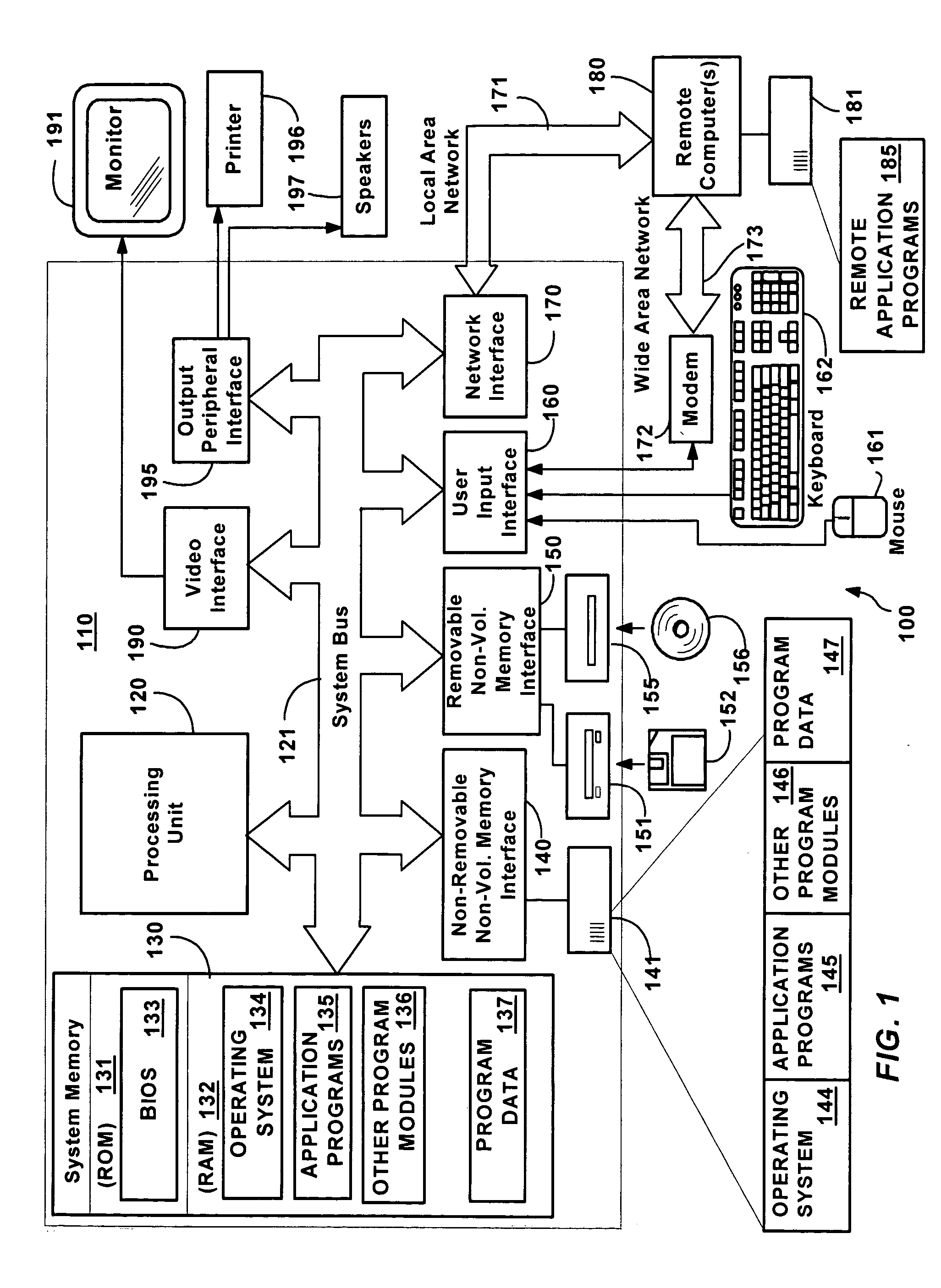
FIG. 1 illustrates an example of a suitable computing system environment 100 on which the invention may be implemented. The computing system environment 100 is only one example of a suitable computing environment and is not intended to suggest any limitation as to the scope of use or functionality of the invention. Neither should the computing environment 100 be interpreted as having any dependency or requirement relating to any one or combination of components illustrated in the exemplary operating environment 100.

The invention is operational with numerous other general purpose or special purpose computing system environments or configurations. Examples of well known computing systems, environments, and / or configurations that may be suitable for use with the invention include, but are not limited to, personal computers, server computers, hand-held or laptop devices, multiprocessor systems, microprocessor-based systems, set top boxes, programmable consumer electronics, network PCs,...


PUM


Abstract

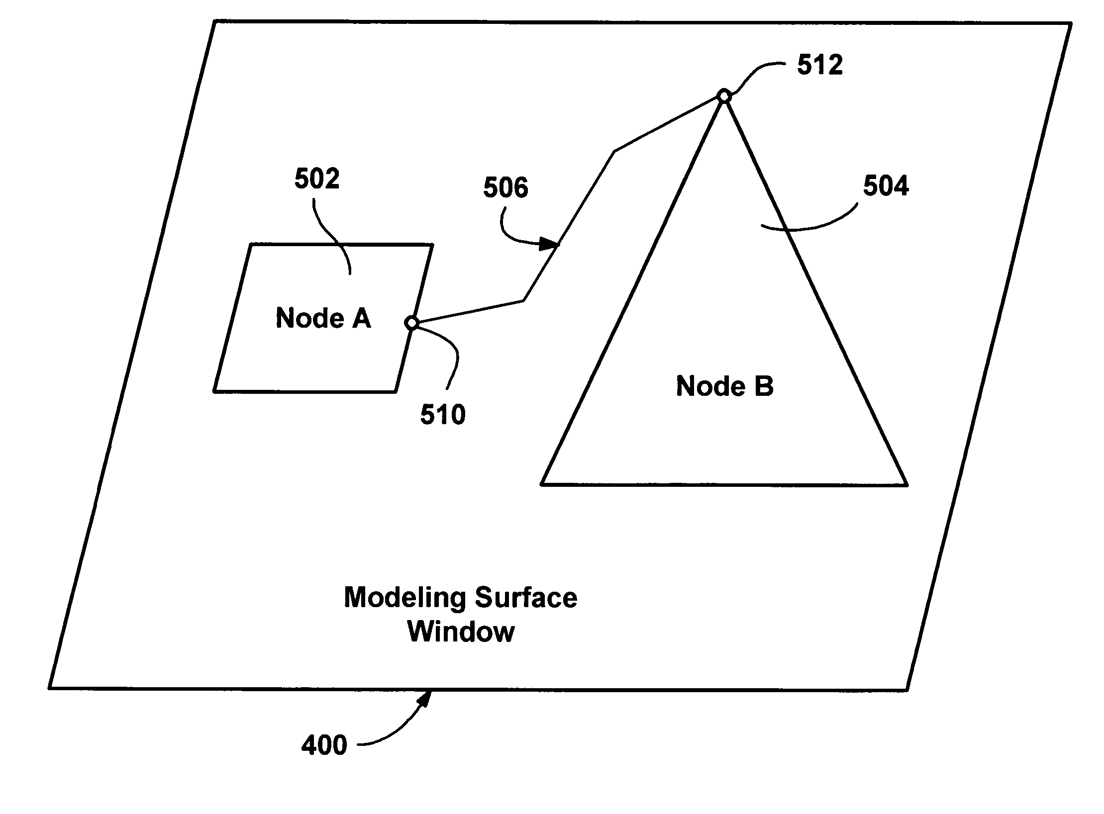
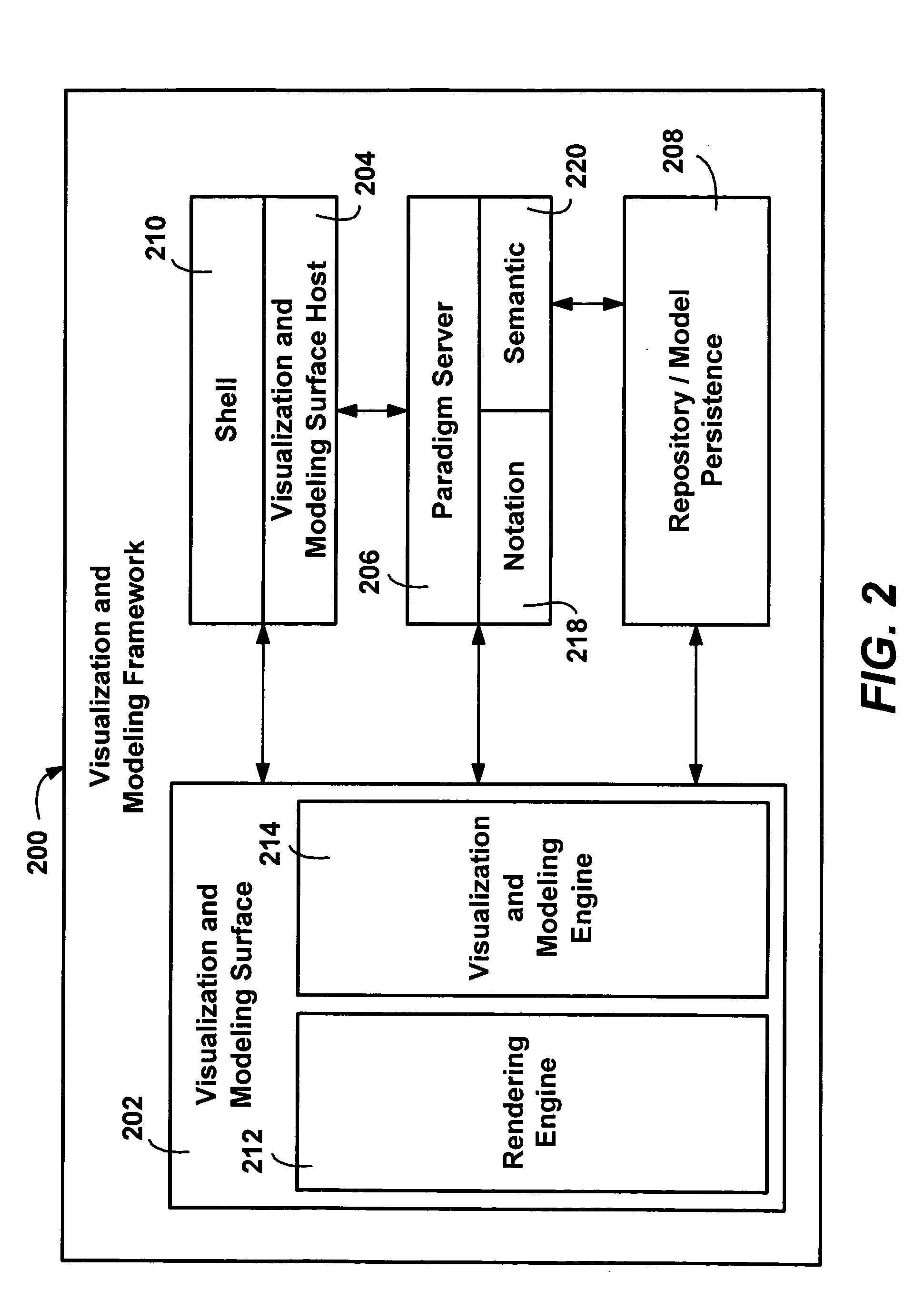
Described is a method and system providing a dynamic, live (active) surface and/or model elements to complement and enhance what is being modeled or visualized, enabling the addition of new features and functionality to visualization and modeling tools. A dynamic surface is accomplished by extending traditional HTML, rendering APIs and/or components to enable visualization and modeling functionality. The surface background and model elements may comprise HTML elements, and the surface can include a Web site. The model elements are HTML elements layered dynamically atop the surface, as the user interacts with them, and completed designs may be saved in a non-proprietary format, (e.g., HTML). The live surface bases its services on HTML rendering engine services, and further provides a visualization and modeling engine that wraps and extends the rendering engine through multiple interfaces. Interfaces can enumerate modeling elements and their relationships, add, delete or change connections between model elements and states, and initialize the surface, including loading an existing diagram such as saved as an HTML document.

Description

FIELD OF THE INVENTION The present invention is generally directed to computer systems, and more particularly to visualization and modeling in computer systems. BACKGROUND OF THE INVENTION Visualization and modeling software is extensively used in industry. Visualization generally refers to computer tools for viewing existing layouts, such as for viewing a representation of a network topology, an electrical wiring system or various other things that are designed. Visualization has general relevance in various applications, e.g., viewing a network topology is a scenario that is applicable to many different products. Modeling refers to computer tools used to design things, such as software, databases, integrated circuits, CAD / CAM applications and the like. Thus, in general, in visualization, a user looks at interconnected model elements placed on a viewing surface. In modeling, a user places the model elements on a work surface and connects them together in some manner. The semantic...

Claims


Application Information

Patent Timeline
IPC IPC(8): G06F9/44G06T15/00
CPCG06T15/00G06F9/4443G06F9/451
Inventor RAJARAJAN, VIJKIERNAN, CASEY L.MACLEOD, STEWART P.OBERST, SHAWN E.
Owner MICROSOFT TECH LICENSING LLC
Why Eureka
Try Eureka