
Electronic device having stopwatch and heat index indicator functionality

a technology of electronic devices and functions, applied in mechanical clocks, instruments, horology, etc., can solve the problems of cumbersome equipment and inability to easily monitor the hi easily, and achieve the effect of prolonging exposure and prolonging exposur

Inactive Publication Date: 2005-02-24
FLIR SYST INC
View PDF6 Cites 0 Cited by
  • Summary
  • Abstract
  • Description
  • Claims
  • Application Information

AI Technical Summary

Benefits of technology

An alternate method is to refer to readily available tables listing the HI for specific temperatures and RH. The data from these tables can be stored in the memory of the inventive instrument, for example in a look-up table that is used to determine the HI. These tables can also indicate to the user the severity of exposure to a specific HI.
Heat Index / Heat Disorders Heat Index / Heat DisordersHeatPossible heat disorders forIndexpeople in higher risk groups130° F. orHeatstroke / sunstroke highly likely with continuedhigherexposure.105°-Sunstroke, heat cramps or heat exhaustion likely, and130° F.heatstroke possible with prolonged exposure and / orphysical activity.90°-Sunstroke, heat cramps and heat exhaustion possible105° F.with prolonged exposure and / or physical activity.80°-Fatigue possible with prolonged exposure and / or90° F.physical activity.
The “Heat Index / Heat Disorders” table relates ranges of HI with specific disorders, particularly for people in the higher risk groups.

Problems solved by technology

Present methods of determining the heat index (HI) require cumbersome equipment such as a sling psychrometer and a thermometer to measure the relative humidity (RH) and temperature, respectively, and at least tables to determine the HI.
Also, using these methods it is not possible to continuously monitor the HI easily.

Method used


Image

  • Electronic device having stopwatch and heat index indicator functionality
  • Electronic device having stopwatch and heat index indicator functionality

Examples


Embodiment Construction

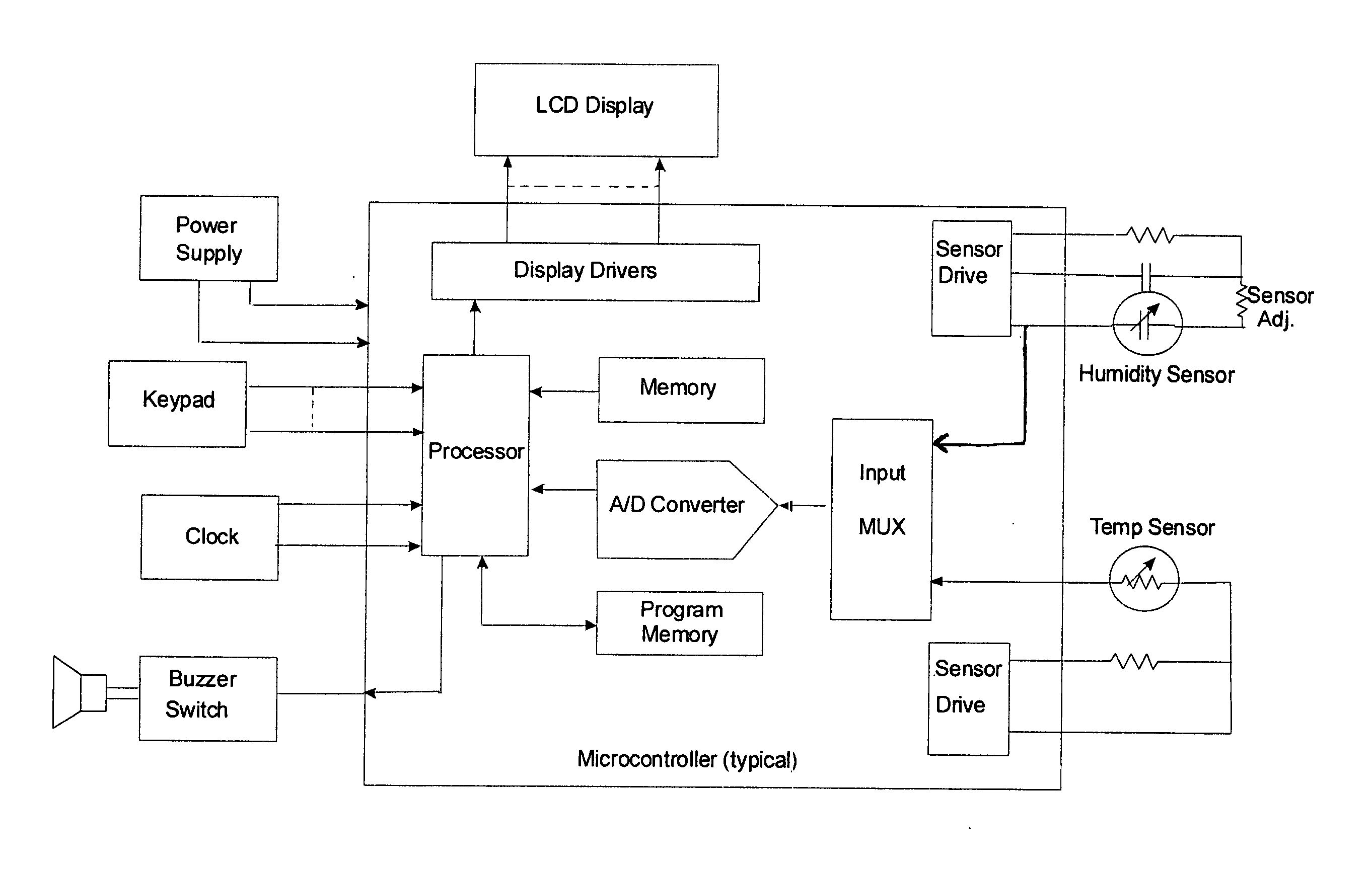
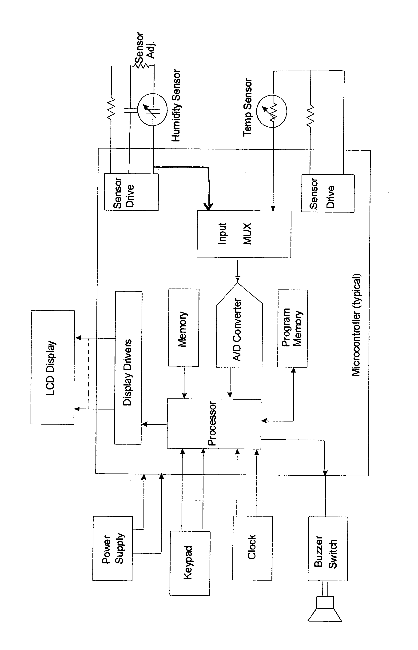
The following description is of the preferred embodiment of the invention, shown in the attached FIGURE. It consists of a microcontroller that includes any necessary analog-to-digital converters, display drivers, keypad interface, functional program, memory, microprocessor calculating capability, and alarm driver. There are many other embodiments that would be obvious to anyone knowledgeable in these areas. In many cases, the functions included in the microcontroller could instead be performed by individual external devices. The LCD display in this embodiment can be replaced by other display technology such as LEDs. The device has typical stopwatch functionality as described above, the details of which are known in the art.

The power supply provides power for the microcontroller and all other devices as required. The keypad is used to step through the various functions, input the HI alarm setpoint, set up the parameters (such as ° C. or ° F.), and determine the display mode (e.g.,...


PUM

PropertyMeasurementUnit
relative humidityaaaaaaaaaa
temperatureaaaaaaaaaa
humidityaaaaaaaaaa

Abstract

An electronic device including a multimode electronic stopwatch having a digital display and programmable integrated circuit programmed to keep time and to provide a plurality of timepiece operating modes. The device includes a humidity sensor for acquiring relative humidity information, and a temperature sensor for acquiring ambient temperature information. The integrated circuit also determines a heat index value based on the temperature and humidity information. The device has a display for displaying to the user the determined heat index value, and an alarm for notifying the user when a particular heat index level is reached.

Description

FIELD OF THE INVENTION The invention relates generally to multimode digital electronic timepieces such as stopwatches that display date, time and stopwatch information, and more particularly to a timepiece capable of displaying temperature, humidity and heat index information and providing a user alarm when the heat index reaches a level preset by the user. BACKGROUND OF THE INVENTION Present methods of determining the heat index (HI) require cumbersome equipment such as a sling psychrometer and a thermometer to measure the relative humidity (RH) and temperature, respectively, and at least tables to determine the HI. Also, using these methods it is not possible to continuously monitor the HI easily. SUMMARY OF THE INVENTION It is therefore a primary object of this invention to provide a handheld instrument that includes the functionality of a stopwatch and also determines and reports to the user the heat index, preferably along with an alarm that notifies the user when a particul...

Claims


Application Information

Patent Timeline
Patent Type & Authority Applications(United States)
IPC IPC(8): B32B3/02G04B47/06G04F10/00G04G21/02
CPCG04G21/02G04F10/00
Inventor BLAKELEY, GERALD W. III
Owner FLIR SYST INC
Learn More