System and method for automated engineering of optical networks

a technology of optical network and automatic engineering, applied in the field of computer modeling of optical network, can solve the problems of complex iterative process of manual modification and analysis, high cost, time-consuming and expensive, and the network configuration resulting from similar analyses is often inconsisten

Active Publication Date: 2005-02-24
CIENA
View PDF2 Cites 21 Cited by
  • Summary
  • Abstract
  • Description
  • Claims
  • Application Information

AI Technical Summary

Benefits of technology

[0008] In one aspect, the invention features a computerized method for modifying an optical WDM network. The method includes providing an initial configuration of the optical WDM network and evaluating at least one parameter that represents a characteristic of a span in the optical WDM network as defined by the initial configuration. The method also includes modifying the initial configuration of the optical WDM network in response to the evaluation of the one or more parameters. In one embodiment, the method also includes determining if a predetermined set of engineering rules are satisfied. In other embodiments, the evaluation of the at least one parameter includes evaluating a value of chromatic dispersion, polarization mode dispersion, optical signal to noise ratio or crosstalk for the span. In another embodiment, the evaluation of the at least one parameter includes evaluating an optical power at a receiver in the span. In still other embodiments, the modification of the initial configuration includes adjusting a placement in the span of an optical regenerator, or an optical amplifier, or inserting an optical regenerator or an optical amplifier in the span. In yet another embodiment, the modification of the initial configuration includes adjusting at least one setting of equipment in the optical WDM network.

Problems solved by technology

The iterative process of manual modifications and analysis is complicated, time consuming and requires highly trained engineers.
Consequently, the process is expensive.
Moreover, because the process depends on the individual expertise and bias of the network engineers, the network configurations resulting from similar analyses are often inconsistent.
The process is complex even for small networks because modifying a single network component can cause numerous changes to optical signal parameters on the connected links or on other links in the network.
For example, optical amplifiers are used to extend the range of an optical signal by increasing the signal power, however, optical amplifiers increase the amplified spontaneous emission (ASE) noise of the signal.
The ASE noise can be addressed by using equalization techniques, however, additional noise and optical power problems can arise.

Method used


Image

  • System and method for automated engineering of optical networks
  • System and method for automated engineering of optical networks
  • System and method for automated engineering of optical networks

Examples


Embodiment Construction

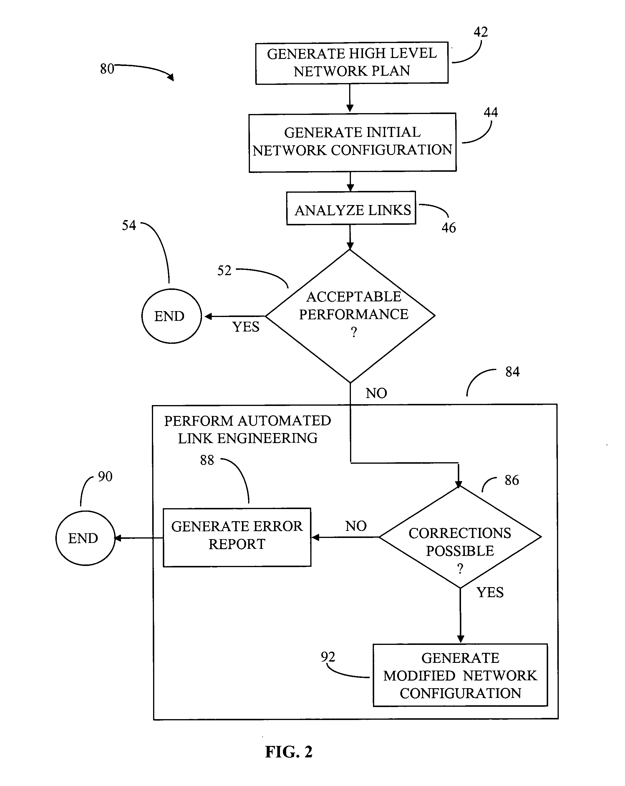
[0018]FIG. 2 shows an embodiment of a process 80 that automatically modifies a wavelength division multiplexing (WDM) network design. In one embodiment, the process is performed by a software module that is integrated into a software engineering environment. The process 80 includes generating (step 42) a high level network plan. Typically, the high level network plan is generated by identifying the required performance parameters of the network such as the data rates, channel densities and the number of access nodes. An initial configuration for a network is then generated (step 44) by selecting various network equipment and components, and determining where to locate them in the network. This step generally relies on the experience of the individual network engineer. Thus different engineers do not usually select the same initial configuration for the network. In some instances, the initial configuration can be a previously derived network configuration.

[0019] The initial configur...


PUM


Abstract

A computerized method for modifying an optical wavelength division multiplexing (WDM) network is described. The method includes providing an initial configuration of the optical WDM network. At least one parameter that represents a characteristic of a span in the optical WDM network as defined by the initial configuration is evaluated. The initial configuration of the optical WDM network is modified in response to the evaluation. The method can also include determining if a predetermined set of engineering rules are satisfied.

Description

CROSS-REFERENCE TO RELATED APPLICATON [0001] This application claims the benefit of the filing date of co-pending U.S. provisional patent application Ser. No. 60 / 493,683, filed Aug. 8, 2003, titled “System and Method for Automated Engineering of Optical Networks,” the entirety of which provisional application is incorporated by reference herein.FIELD OF THE INVENTION [0002] The invention relates generally to the computer modeling of optical networks. More particularly, the invention relates to a system and method that automatically modifies an optical wavelength division multiplexing (WDM) network to improve performance. BACKGROUND [0003] The task of engineering a WDM network consists of identifying the appropriate type of equipment, the appropriate location of the equipment, and specifying the required settings of the equipment so that optical signals transmitted through the network have satisfactory optical characteristics. Computer modeling software can be used to aid in engineer...

Claims


Application Information

Patent Timeline
Patent Type & Authority Applications(United States)
IPC IPC(8): H04J14/02
CPCH04J14/0221H04J14/0227H04J14/025H04J14/0246H04J14/0283
Inventor MOFFATT, GREGORYWAKEFIELD, JOANNECOLEMAN, THOMASRILEY, MARKHUBBARD, CHARLES
Owner CIENA
Why Eureka
Try Eureka