Battery terminal and method for making the same

a battery terminal and battery case technology, applied in the field of battery terminals, can solve the problems of acid solution leaking out of the battery case, unsatisfactory resistance to rotation, etc., and achieve the effects of minimizing or preventing fluid leakage, reducing corrosion, and improving torque-turning resistan

Inactive Publication Date: 2005-02-24
JOHNSON CONTROLS TECH CO
View PDF13 Cites 24 Cited by
  • Summary
  • Abstract
  • Description
  • Claims
  • Application Information

AI Technical Summary

Benefits of technology

[0007] One advantage of the present invention is that it provides an exterior (i.e., on the outside of the battery case) spin riveted terminal to eliminate the interior (i.e., interior of the battery case) lead cold working to thereby minimize corrosion as described in the Background, and the accompanying leakage associated therewith. Another advantage of the present invention is that it provides an anti-rotation arrangement of interlocking bosses/slots that provide a torque-turning resistance that is improved over conventional approaches taken in the art. Another advantage of the present invention is that it provides a battery terminal having a sealing system configured to seal the battery terminal area to thereby minimize or prevent leakage of fluid, such as sulfuric acid solution. Still another advantage according to the present invention is that it provides a battery terminal having a mechanism for minimizing or eliminating acid stratification, which minimizes corrosion (as described in greater detail hereinafter).
[0008] A battery terminal according to the invention is configured to be secured to a battery case from an exterior side thereof. The battery terminal comprises a terminal assembly, a ring, and a terminal anti-rotation system. The terminal assembly extends generally along a main axis and includes (i) an insert having a threaded bore and (ii) an outer metal portion having a base with an annular flange configured to engage an inner surface of the case. The term...

Problems solved by technology

The anti-rotation approach in Spiegelberg et al., however, does not provide satisfactory resistance to rotation in certain circumstances and the sealing approach requires a complicated insert molding process or the like.
However, it has been...

Method used


Image

  • Battery terminal and method for making the same
  • Battery terminal and method for making the same
  • Battery terminal and method for making the same

Examples


case 16

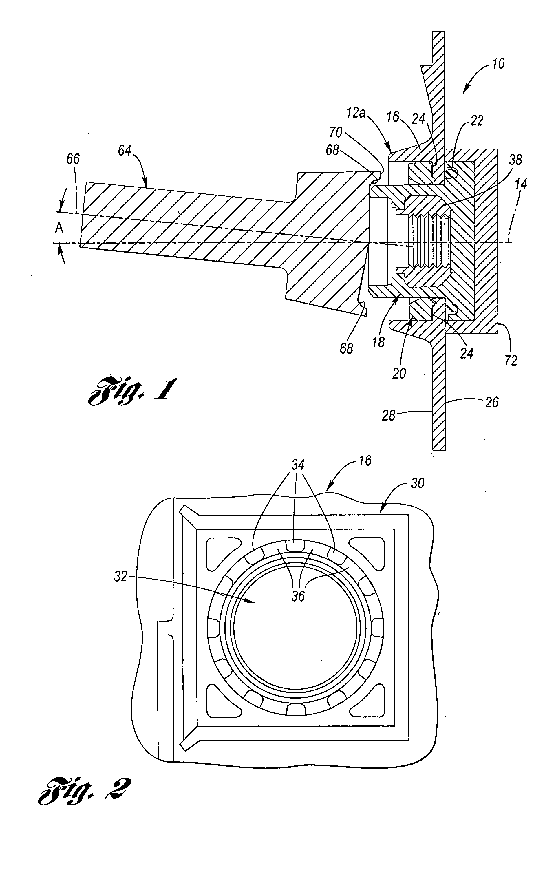
[0020] Case 16 is configured generally to retain the inner components of battery 10, and may comprise conventional, electrical insulating material, such as various plastics (e.g., polypropylene). As shown in FIG. 1, battery case 16 includes an inner or inside surface 26, and an outer or outside surface 28. For reference, inner surface 26 faces the interior of storage battery 10, and is configured to, during the service life of storage battery 10, come into contact with sulfuric acid solution, for example.

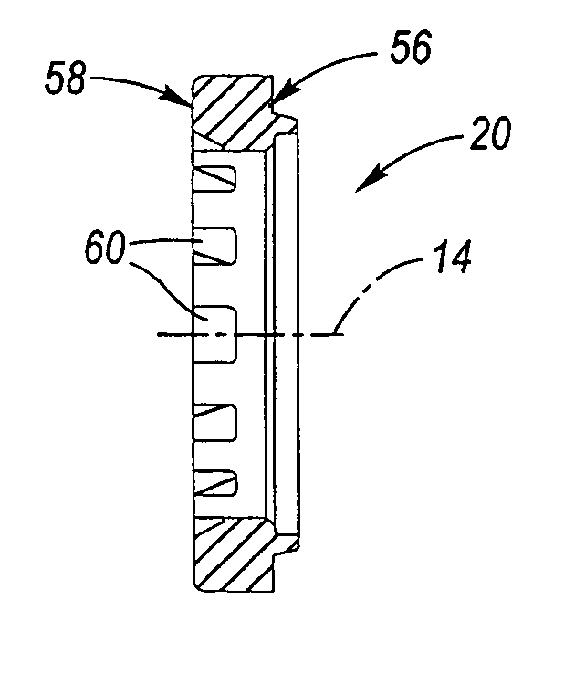
[0021] Referring to FIG. 2, battery case 16 further includes a pair of main bosses 30 (only one shown in FIG. 2) that are configured, generally, to cooperate with the components described herein to form the battery terminal 12. Main boss 30 includes a central through-bore 32, and a set of angularly-spaced lands or bosses around bore 32, separated by and raised relative to, intervening slots 36. As will be described in greater detail below, bosses 34 and slots 36 form part of a termi...


PUM


Abstract

A battery terminal is configured to be secured to a battery case and includes a terminal assembly, and a ring. The terminal assembly includes an insert having a threaded bore, and an outer metal portion having a base with an annular flange configured to engage the inner surface of the case. The terminal further includes an anti-turn system with a first set of angularly-spaced bosses with intervening slots formed on a boss on the case, a second set of angularly-spaced bosses with intervening slots on a first side of the ring facing the case, which are complementary to the first set to form interlocking features. A set of recesses on the opposite side of the ring is configured to receive spun-over lead material during final finishing to form another pair of interlocking features. The exterior spun battery terminal eliminates corrosion that would otherwise occur due to cold worked lead contacting acid.

Description

BACKGROUND OF THE INVENTION [0001] 1. Technical Field [0002] The present invention relates generally to a battery terminal and a method for making the same. [0003] 2. Description of the Related Art [0004] It is known generally to provide an electric storage battery of the type having external terminals on the side or end walls of the battery case. Typically, such terminals are not of the post type, but rather are of the recessed, threaded female type terminal, as seen by reference to U.S. Pat. No. 5,814,421 to Spiegelberg et al. Spiegelberg et al. disclose a method for forming such a battery terminal having a threaded hard metal insert received within an outer portion formed of lead, the lead portion being deformed (i.e., cold worked) by an orbital head-forming apparatus to secure the hard metal insert within the outer lead portion. Spiegelberg et al. further disclose that the outer portion includes a spline ring to prevent rotation of the terminal within the battery housing. Spiege...

Claims


Application Information

Patent Timeline
IPC IPC(8): H01M10/06H01M50/188H01M50/193
CPCH01M2/08H01M10/06H01M2/307Y02E60/10H01M50/561H01M50/193H01M50/188
Inventor KEY, TONY E.BARCLAY, JOHN BLACK JR.KENSINGER, STEVEN G.
Owner JOHNSON CONTROLS TECH CO
Why Eureka
Try Eureka