
Automatic gear system

a transmission system and automatic technology, applied in the direction of gearing control, gearing elements, belts/chains/gearings, etc., can solve the problem of not being able to ensure that the torsional forces corresponding to the predetermined maximum synchronization force prescribed by the manufacturer are not exceeded

Inactive Publication Date: 2005-02-24
SCHAEFFLER TECH AG & CO KG
View PDF12 Cites 21 Cited by
  • Summary
  • Abstract
  • Description
  • Claims
  • Application Information

AI Technical Summary

Benefits of technology

[0006] According to one aspect of the present invention, a method for regulating a gear engagement mechanism of an automated multiple-ratio transmission, which has a drive shaft and at least one synchronizer, includes the application of a load to the synchronizer in order to engage or disengage a gear step of the transmission, whereby the load that acts on the synchronizer is calculated as a function of a transmission parameter that changes over time, for example, the rate of change of the drive shaft speed. For this purpose, the monitoring of the drive shaft speed directly via a transmission input speed sensor or the indirect determination of it via additional sensors and measured values, for example of gear information, at least one speed sensor, one clutch travel sensor, one engine speed sensor and / or one throttle flap position as well as the evaluation of stored and / or adaptable value groups of an engine characteristic map may be advantageous.

Problems solved by technology

However, such changes can only be approximations and, while the regulation of the actuation force on the synchronizers is improved, it cannot be guaranteed that the torsional forces corresponding to the predetermined maximum synchronization forces prescribed by the manufacturer are not exceeded.
Furthermore, other factors, such as the wear of the components mounted on the transmission drive shaft, and especially a driven clutch plate, and changes in the friction coefficient of the synchronizer that are not foreseeable and are not precisely applicable for the adjustments also have effects on the torque that is applied by the synchronizer and on the rate of change of the drive shaft speed.

Method used


Image

  • Automatic gear system
  • Automatic gear system
  • Automatic gear system

Examples


Embodiment Construction

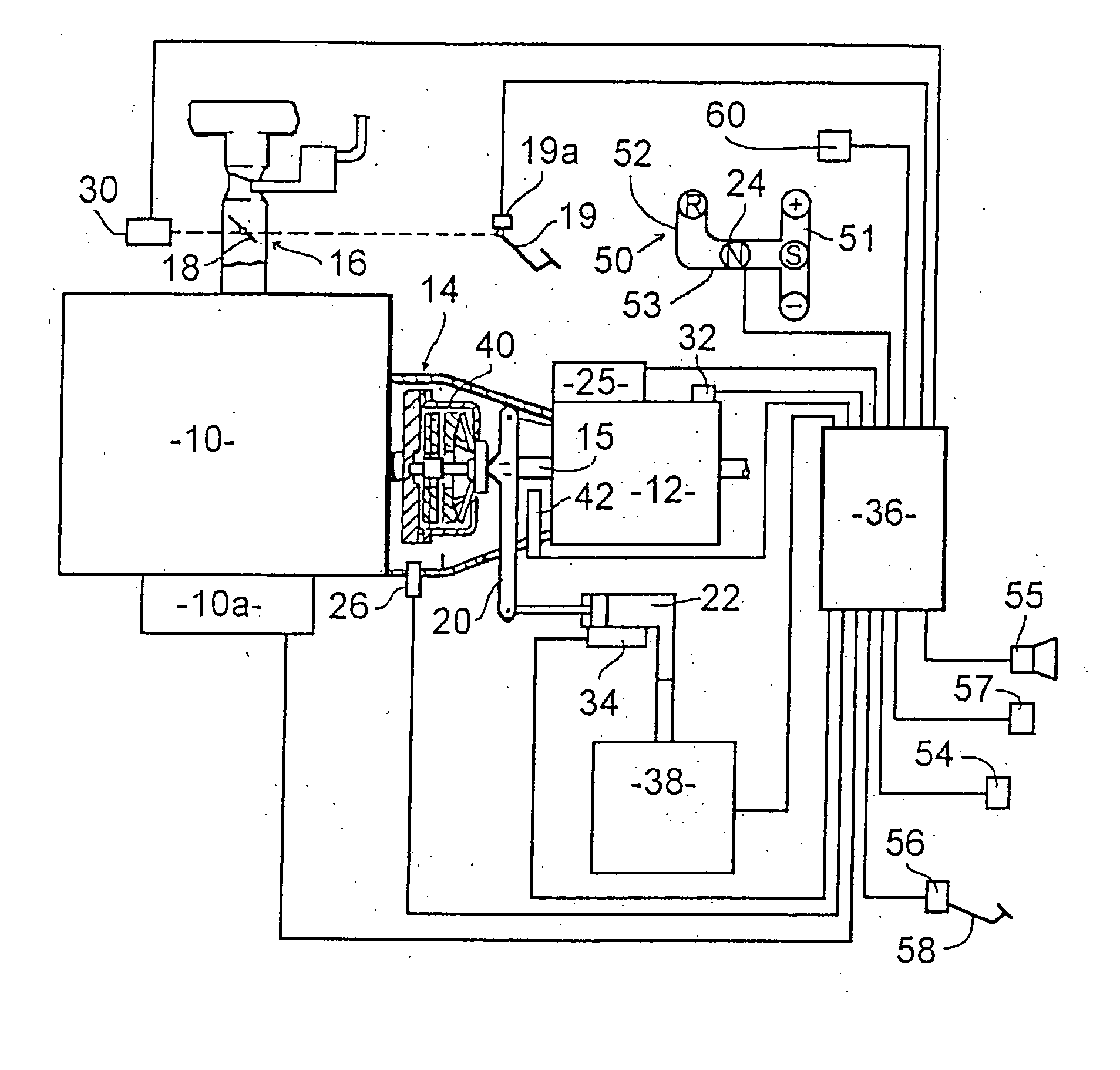
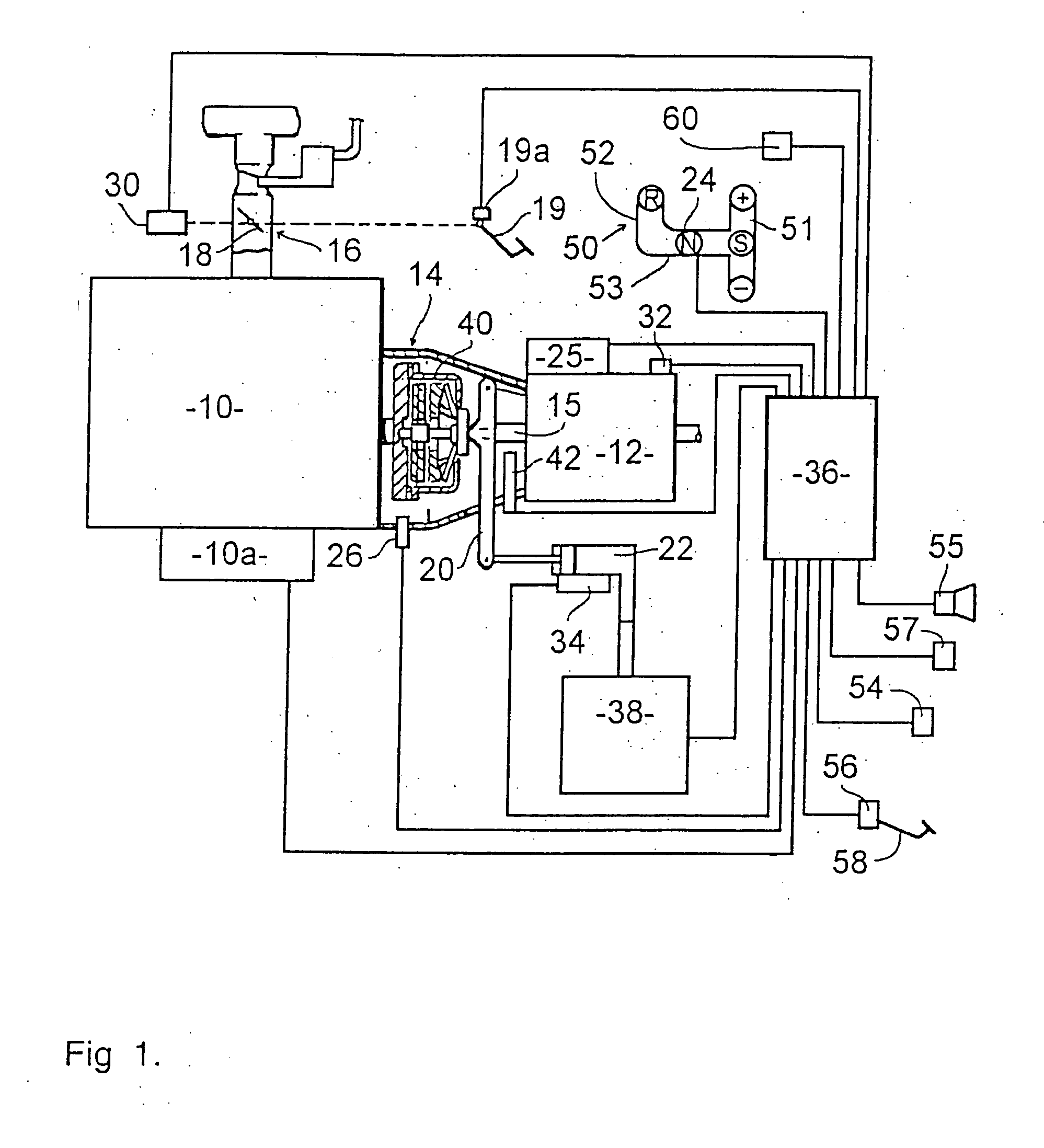
[0014]FIG. 1 of the accompanying drawings shows an engine 10 having a starter and an associated starter circuit 10a that is coupled by main drive friction clutch 14 via a transmission drive shaft 15 to a multiple-ratio, synchronized transmission 12 of the type having a countershaft. The engine is supplied with fuel via a throttle flap 16, the throttle flap comprising a throttle valve 18 that is actuated by gas pedal 19. The invention is equally applicable for gas or diesel engines with electronic or mechanical fuel injection.

[0015] Clutch 14 is actuated by a clutch fork 20 that is actuated in turn by a sequence-controlled hydraulic cylinder 22 that is under the control of a clutch actuator control mechanism 38.

[0016] A gear selection lever 24 operates in a shift gate 50 having two legs 51 and 52 that are linked by a transverse track 53 that extends between the end of leg 52 and a position between the ends of leg 51. Shift gate 50 defines five positions; “R” at the end of leg 52; “...


PUM


Abstract

The invention relates to an automated gear shift system for a multiple-ratio transmission having a synchronizer and a method for this purpose.

Description

BACKGROUND OF THE INVENTION [0001] The present invention relates to automated transmission systems, and in particular automated manual, semi-automatic and fully automatic transmission systems that use a multiple-ratio transmission that has synchronizers on the gear steps. [0002] In automated transmission systems that use multiple-ratio transmissions in which the engagement of the gears is regulated by synchronizers, as are disclosed in, for example, GB2308413; GB2354296; GB2354295; GB2358443; GB0105186.1; GB0029453.8; GB0026423.4; GB0025848.3; GB0025847.5; GB0029454.6; GB0025000.1; GB0024999.5; GB0026178.4; GB0027640.2; GB0028310.1; GB0031624.0; GB103312.5, whereby reference will be made exclusively to these disclosures and their content is incorporated in the disclosure content of the present application; the synchronizer is used to brake or accelerate the drive shaft of the transmission until the speed for the intended target gear is reached. Therefore, the synchronizer, as far as...

Claims


Application Information

Patent Timeline
Patent Type & Authority Applications(United States)
IPC IPC(8): F16H61/28
CPCF16H61/2807F16H61/682F16H2061/2823Y10T74/1926Y10T477/65Y10T477/653Y10T477/6937Y10T74/19251F16H61/04
Inventor KENNEDY, IAN DUNCAN
Owner SCHAEFFLER TECH AG & CO KG
Learn More