Flexible inflow/outflow cannula and flexible instrument port

a flexible, inflow/outflow technology, applied in the direction of surgical forceps, infusion syringes, surgery, etc., can solve the problem that the fluid flow through the rigid cannula is frequently blocked by anatomical structures

Inactive Publication Date: 2005-02-24
CANNUFLOW INC
View PDF11 Cites 134 Cited by
  • Summary
  • Abstract
  • Description
  • Claims
  • Application Information

AI Technical Summary

Benefits of technology

[0009] The instrument port also includes a duckbill valve, flapper valve or trumpet valve disposed in the proximal portion of the instrument port. The valve prevents fluid from flowing past the valve as instruments are inserted into and removed from the cannula. The instrument port is also provided with a fluid port to optionally drain fluid from or introduce fluid into the instrument port.

Problems solved by technology

The rigid cannula can cause problems during the surgical procedure.
Manipulating the patient's joint with the rigid cannula in the operating site can cause significant problems.
In addition, the flow of fluid through the rigid cannula is frequently blocked by anatomical structures.

Method used


Image

  • Flexible inflow/outflow cannula and flexible instrument port
  • Flexible inflow/outflow cannula and flexible instrument port
  • Flexible inflow/outflow cannula and flexible instrument port

Examples


Embodiment Construction

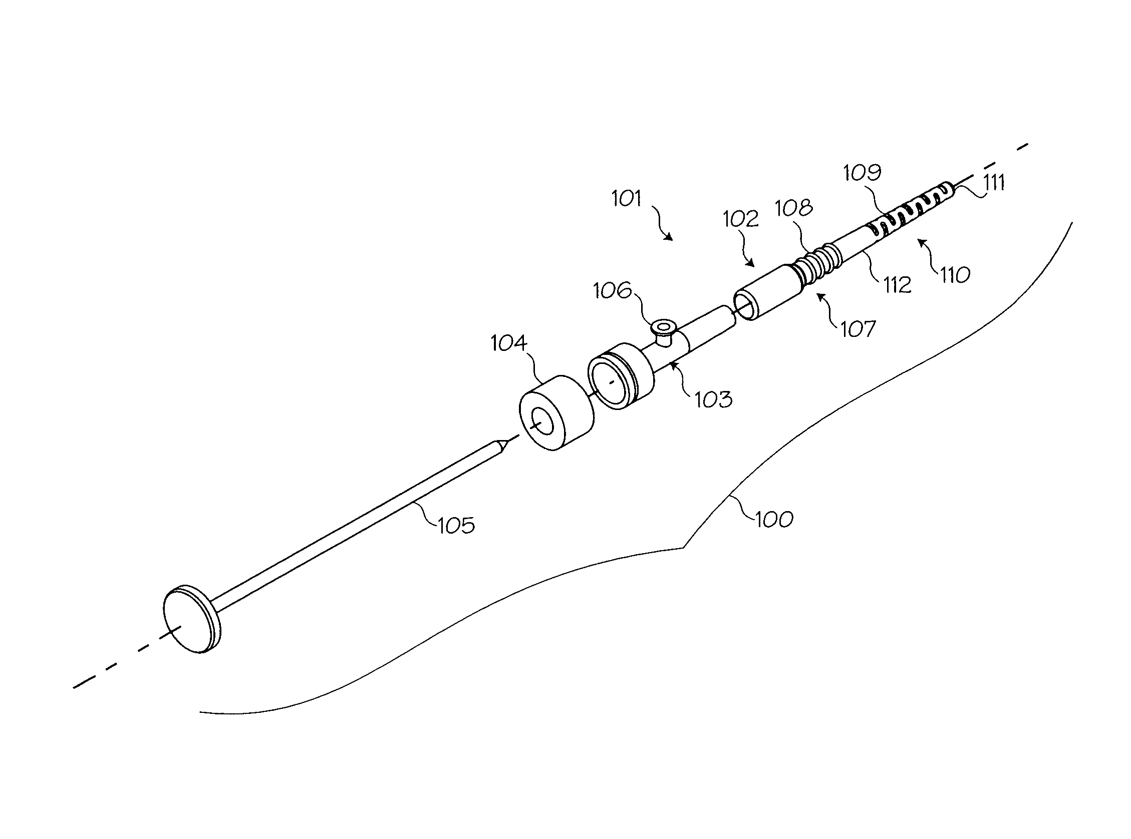
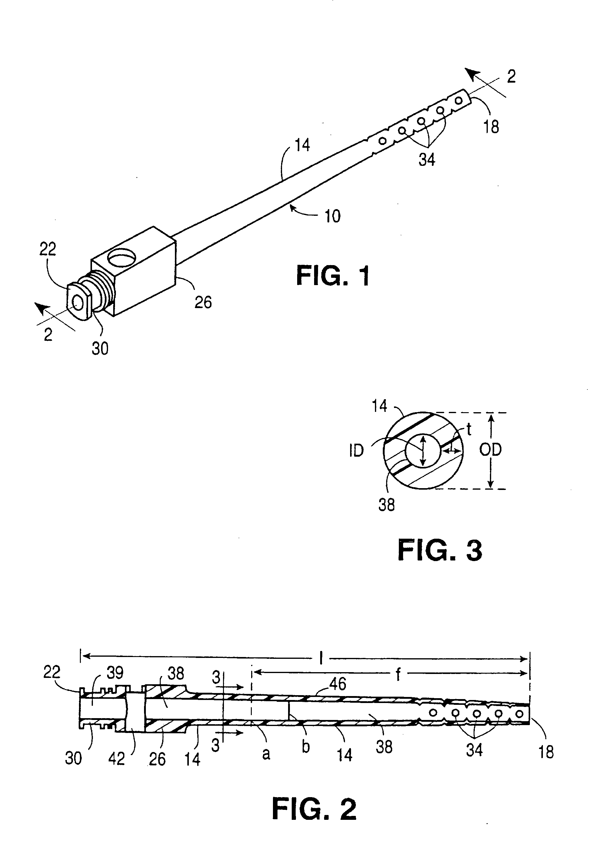
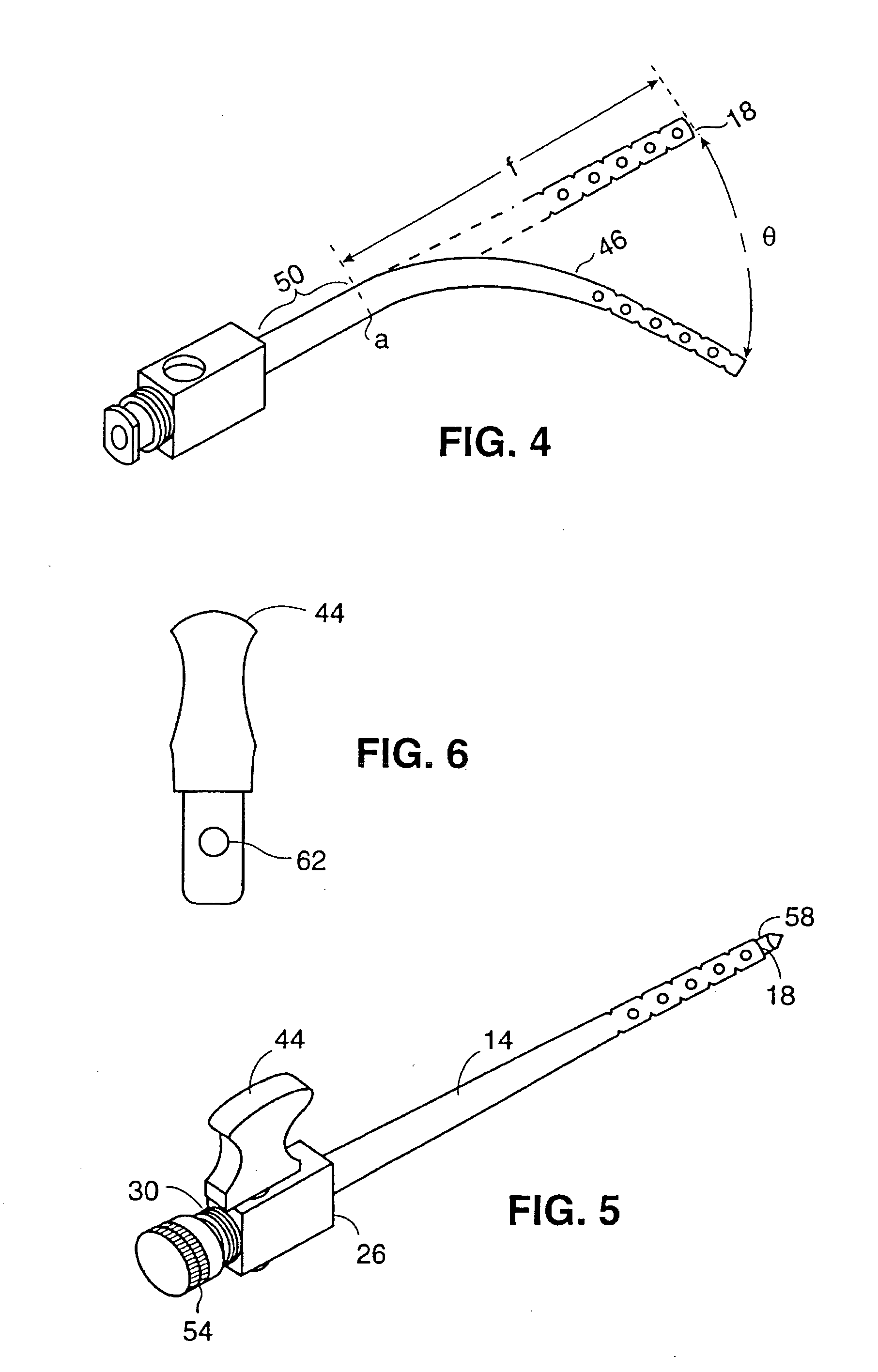
[0026]FIG. 1 illustrates a flexible cannula 10 for use in delivering liquids to or from a surgical field during arthroscopic surgery. The cannula 10 comprises a stem 14, a distal end 18, a proximal end 22, a rigid tube 26 and an attachment means 30. A plurality of apertures 34 are positioned near the distal end 18 of the stem 14. The apertures may be provided with rounded edges to make inserting the cannula into an operating site easier.

[0027]FIG. 2 illustrates that the cannula 10 is a hollow device having a lumen 38 that extends from the distal end 18 through the stem 14, and into the rigid tube 26. A lumen 39 extends from the proximal end 22, through the attachment means 30, and into the rigid tube 26. The cannula 10 has a total length “1” of approximately four inches.

[0028] The lumens 39 and 38 are open at the proximal end 22 and distal end 18, respectively, to provide a means for liquid to enter and exit the cannula 10. Additionally, the apertures, fenestrations or slots 34 ex...


PUM


Abstract

A flexible plastic cannula for use during arthroscopic surgery. The cannula is a flexible elongated tube having longitudinally staggered slots disposed on the distal end of the tube. The tube is tapered along its length so that the proximal portion of the tube is relatively rigid, while the distal end is narrower and more flexible. The tube is sufficiently flexible to allow the tube to bend with a joint during arthroscopic surgery.

Description

FIELD OF THE INVENTIONS [0001] The inventions described below relate the field of cannulas for use in surgical procedures and more particularly to a flexible instrument port for use during arthroscopic surgery. BACKGROUND OF THE INVENTIONS [0002] In arthroscopic surgery, it is common practice to fill the surgical site with clear saline solution (or other clear, inert fluid) in order to keep the field of view through an arthroscope clear. Since even a small amount of blood will cause the surgical site to become cloudy, means for draining and replenishing the irrigation solution are needed throughout the surgery. [0003] For many arthroscopic surgeries, a rigid cannula is provided into the surgical site and is used to deliver irrigation fluid to the site. A tube is attached between the cannula and an elevated fluid reservoir is provided to deliver the fluid to the cannula. In this case, the rigid cannula is known as an inflow cannula. A second cannula or a suction device for draining f...

Claims


Application Information

Patent Timeline
Patent Type & Authority Applications(United States)
IPC IPC(8): A61B17/28A61B17/34A61B18/14A61M1/00A61M3/02
CPCA61B17/3421A61B17/3498A61B18/14A61B2017/2905A61M3/0279A61B2017/3484A61B2217/005A61M1/0084A61B2017/347A61M1/85
Inventor KUCKLICK, THEODORE R.BRUCE, ROBERT P.
Owner CANNUFLOW INC
Why Eureka
Try Eureka