Facet joint prosthesis

a facet joint and prosthesis technology, applied in the field of human spine prosthesis, can solve the problems of degeneration of the facet joint between the vertebrae, low back pain, adverse effects of spinal fusion,

Inactive Publication Date: 2005-02-24
RE SPINE
View PDF8 Cites 225 Cited by
  • Summary
  • Abstract
  • Description
  • Claims
  • Application Information

AI Technical Summary

Benefits of technology

[0026] 1) The contact surface area, the quantity and direction of force transmitted from the inferior articular process of the cephalad vertebra to the superior articular process of the caudad vertebra changes constantly during the normal range of

Problems solved by technology

Another problem associated with low back pain, which often accompanies DDD is degeneration of the facet joints between vertebrae.
Spinal fusion often provides good results but has adverse effects.
In advanced degenerative changes of a spinal motion segment, all three joints (the disc and facet joints) are affected, and replacement of the disc alone will not provide satisfactory results.
A prosthesis that lacks any one of these features will be prone to malfunction or become loose and thereby place untoward stress on the disc and the adjacent levels.
However, because of the very wide variation among individual patients in angle, orientation, size, and shape of the facets, a single set of conical or pyramidal caps will not be capable of matching all bone structures found in various individuals.
Another problem that may be encountered with this design is related to the stability of the implanted prosthetic device.
Simple fixation of the caps to the underlying articular processes may not withstand repetitive torsional, bending and shear forces.
Furthermore, the inferior component, fastened to the superior articular process, may also not withstand a very high bending moment and shear force.
Finally, the articulating surfaces between the inferior and superior components may not provide stability during torsional motion, especially during compression-torsion motion.
Also this prosthesis may have difficulty in providing a substantial weight bearing function in the axial direction.
In this design, the concentric ball and shallow socket (or saucer) may have difficulty in meeting the abo

Method used


Image

  • Facet joint prosthesis
  • Facet joint prosthesis
  • Facet joint prosthesis

Examples


Embodiment Construction

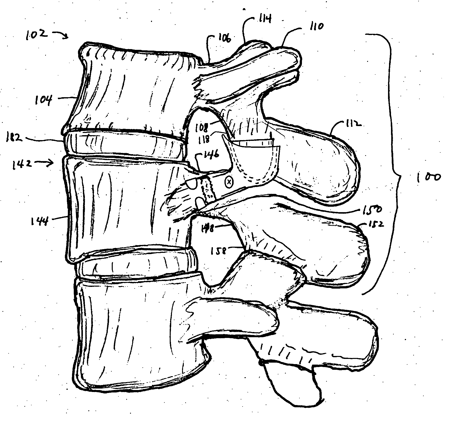
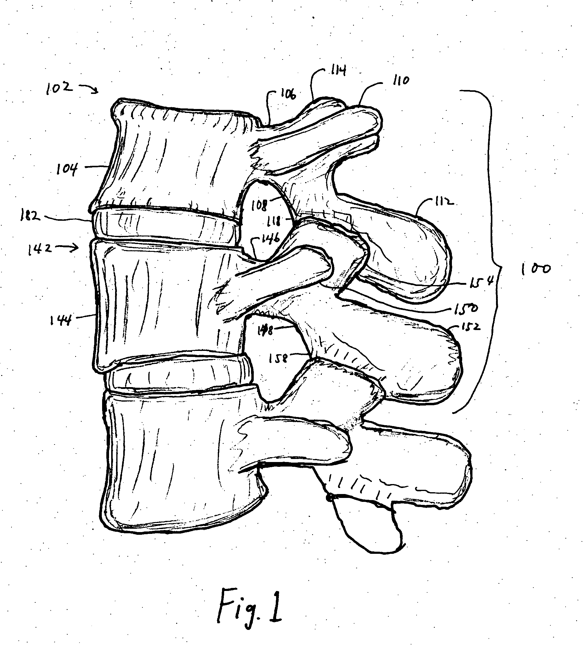
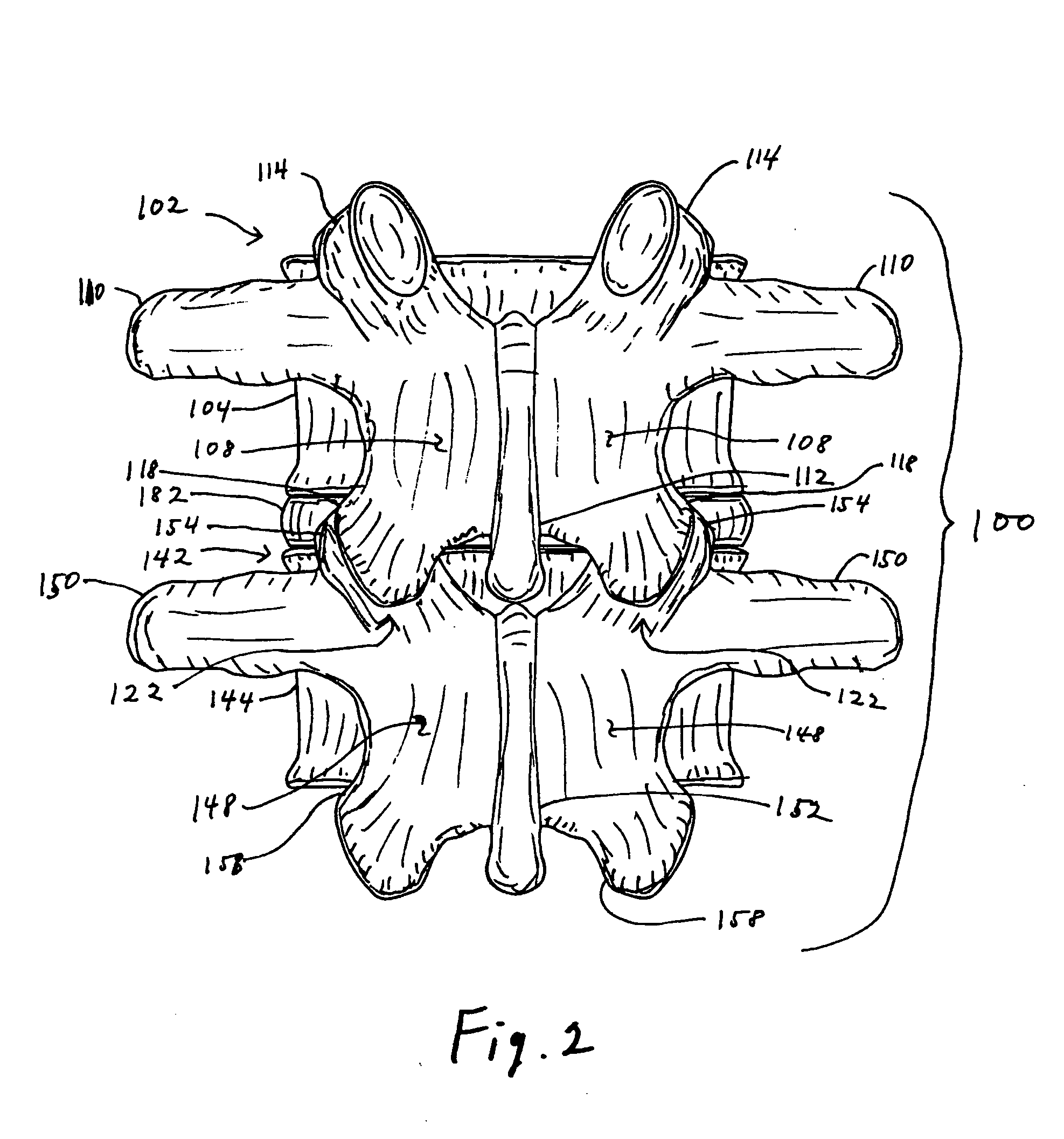
[0064] The design of the improved facet joint prosthesis of the invention is intended to overcome the disadvantages of the previous designs.

[0065] The improved facet joint prosthesis of the invention comprises two articulating elements: [0066] a) a generally conical prosthesis for the inferior articular process of the cephalad vertebra, and [0067] b) a generally cup-shaped prosthesis for the superior articular process of the caudad vertebra that receives the conical prosthesis of the cephalad vertebra.

[0068] The articulating elements of the prosthesis are fixed to their respective vertebrae with appropriate fixation devices. These fixation devices may be of the types conventionally used in spinal prosthesis fixation. Alternatively, one or more of the fixation devices may have a preferred structure as discussed below.

[0069] The conical prosthesis for the cephalad vertebra (“the cone”) has a generally circular cross-section. An interior cavity extending from the base of the cone in...


PUM


Abstract

A prosthetic implant for replacing a facet joint of a spinal motion segment includes a generally conical superior component adapted to be implanted at a surgically prepared site on a lower articular process of a cephalad vertebra of a spinal motion segment, and a cup-shaped inferior component adapted to be implanted at a surgically prepared site on a superior articular process of a caudad vertebra of the spinal motion segment.

Description

CROSS-REFERENCE TO RELATED APPLICATION [0001] This application claims the benefit of the priority of U.S. Provisional Patent Application No. 60 / 487,604, filed Jul. 17, 2003, the entire disclosure of which is incorporated herein by reference.BACKGROUND OF THE INVENTION [0002] 1. Field of the Invention [0003] This invention relates to prostheses for replacing structures of the human spine and more particularly to prostheses for replacing a facet joint. [0004] 2. Brief Description of the Prior Art [0005] Lower back pain is a very common disorder and is responsible for extensive morbidity and lost time at work. The prevalence rate of low back pain is very high, affecting approximately 80% of the general population at some time. Although most patients experience the painful symptoms only occasionally and recover fully, approximately 10% of these patients experience chronic and disabling low back pain in spite of various medical treatments. [0006] The most common cause of chronic disablin...

Claims


Application Information

Patent Timeline
IPC IPC(8): A61B17/68A61B17/86A61F2/00A61F2/30A61F2/44A61F2/46
CPCA61B17/686A61F2/30767A61F2/4405A61F2002/30578A61F2002/30579A61F2310/00179A61F2002/4631A61F2310/00017A61F2310/00023A61F2310/00029A61F2002/30925
Inventor LEE, CASEY K.
Owner RE SPINE
Why Eureka
Try Eureka