
Data processing apparatus

a data processing and apparatus technology, applied in the field of data processing apparatuses, can solve problems such as the delay of next-job processing, and achieve the effect of reducing productivity and increasing overall processing efficiency

Inactive Publication Date: 2005-02-24
KONICA MINOLTA BUSINESS TECH INC
View PDF9 Cites 14 Cited by
  • Summary
  • Abstract
  • Description
  • Claims
  • Application Information

AI Technical Summary

Benefits of technology

[0015] A main object of the present invention is to provide a data processing apparatus that, where a processing request for a second job is received while data for an existing job (hereinafter the ‘current job’) is being compressed or decompressed, can increase overall processing efficiency without a reduction in productivity with regard to the current job.
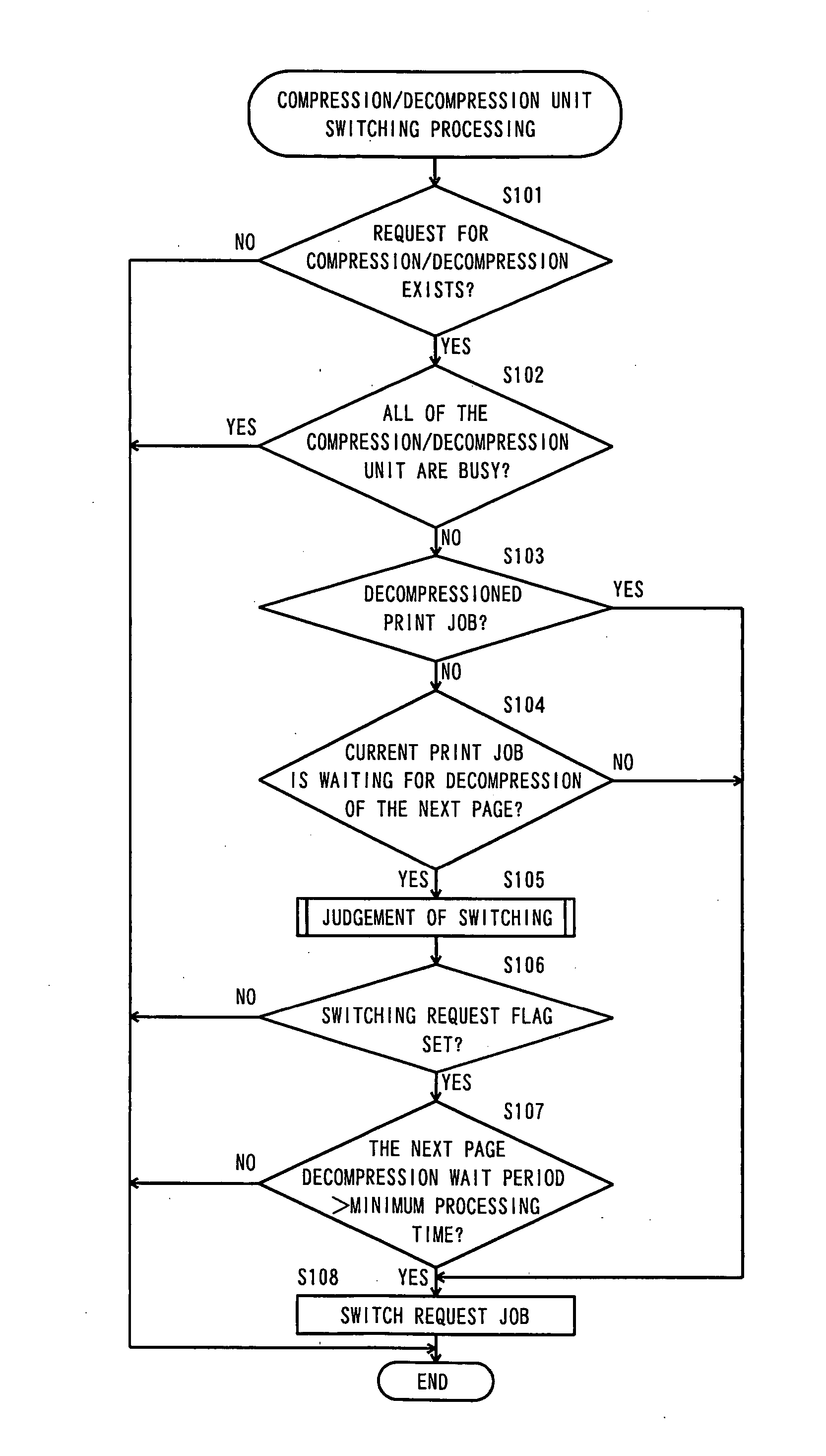
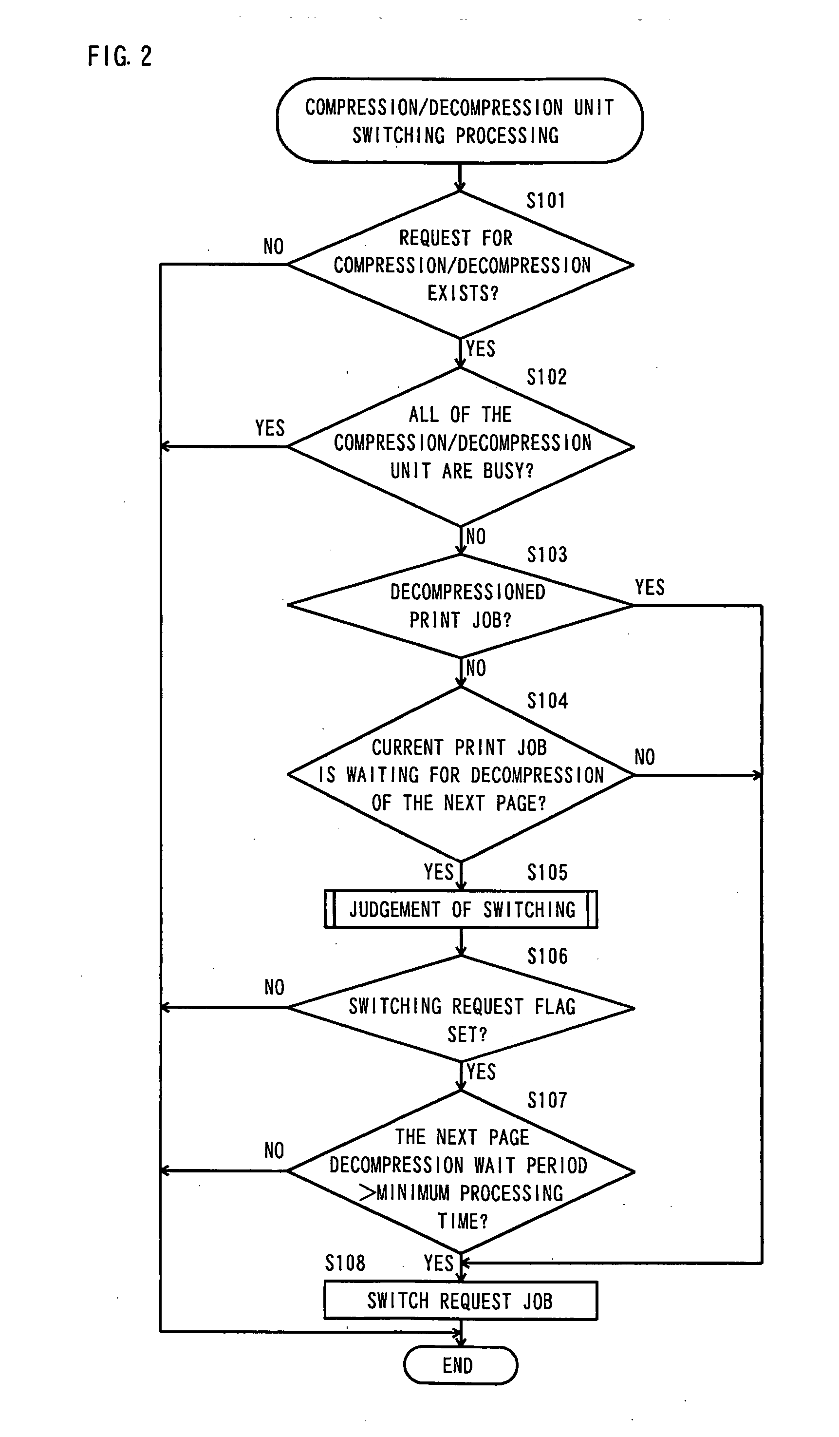
[0020] Because next-job processing is conducted only so long as there is no effect on current job processing as described above, there is no reduction in productivity due to a delay in current-job processing. Furthermore, because the determination as to whether the next-job data will be compressed or decompressed is made based on the result of comparison between the minimum processing time for the next-job data and the processing wait period between pages of the current job, as obtained by processing wait period obtaining means, appropriate processing control is executed irrespective of the type of the next job, and overall processing efficiency for the apparatus is improved.
[0026] Because next-job processing is conducted only so long as there is no effect on current job processing based on the next-job attribute as described above, there is no reduction in productivity due to a delay in current-job processing. Furthermore, because the determination as to whether the next-job data will be compressed or decompressed is made based on the next-job attribute, appropriate processing control is executed and overall processing efficiency for the apparatus is improved.

Problems solved by technology

Conversely, if the processing wait period between pages of the current job is shorter than the minimum processing time for the next-job data, processing of the current job would be delayed by the execution of processing of the next-job data during the processing wait period for the current job, and therefore next-job processing is put on hold.

Method used


Image

  • Data processing apparatus
  • Data processing apparatus
  • Data processing apparatus

Examples


Embodiment Construction

[0040] Embodiments of the present invention will be described below with reference to the attached drawings.

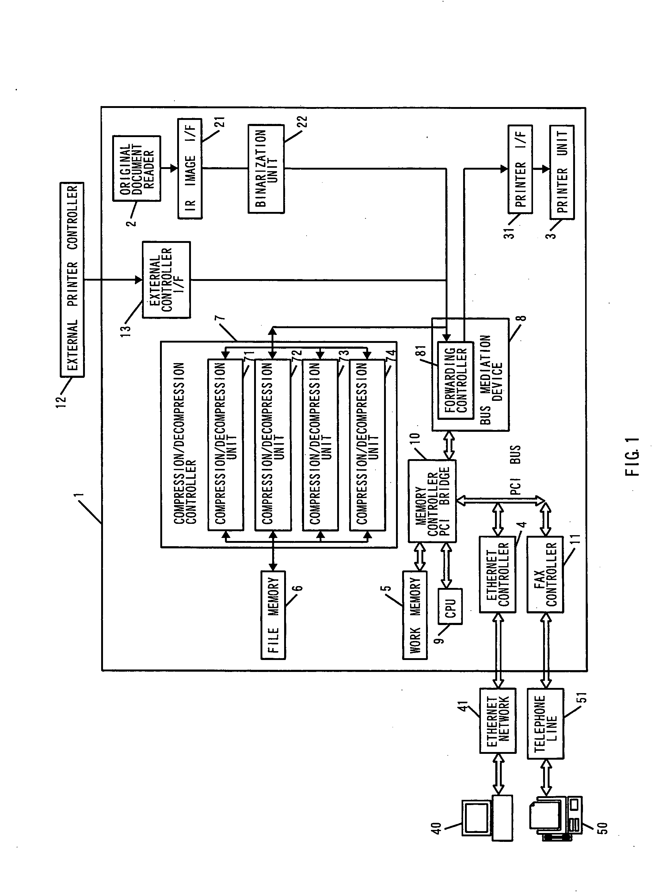
[0041]FIG. 1 is a block diagram of an MFP 1 constituting a data processing apparatus pertaining to an embodiment of the present invention.

[0042] This data processing apparatus includes multiple input means and multiple output means. In other words, it includes an original document reader 2 and an external controller interface (termed an ‘external controller I / F’ in the drawing) 13 that serve as input means, a printer unit 3 that serves as output means, an Ethernet controller 4 that serves both as input means and as output means, and a fax controller 11 that similarly serves both as input means and as output means.

[0043] The original document reader 2 includes a scanner that reads original documents, and the image data for the read original document is sent to a bus mediation device 8 via a read image interface (termed an ‘IR image I / F’ in the drawing) 21 and a binarization ...


PUM


Abstract

When a request for compression or decompression of data for a next job is issued while processing of an current job is underway by one or more compression / decompression unit[s], the minimum processing time for the next-job data is compared with the processing wait period between pages of the current job. It is determined based on the results of this comparison whether or not compression or decompression of the next-job data is to be permitted. Based on this determination, control is carried out regarding whether or not compression or decompression of the next job by the compression / decompression unit[s] between pages of the current job is to be executed.

Description

[0001] The present application claims priority to Japanese Patent Application No. 2003-294572 filed Aug. 18, 2003, the entire content of which is hereby incorporated by reference. BACKGROUND OF THE INVENTION [0002] 1. Field of the Invention [0003] The present invention relates to a data processing apparatus used in a multi-function peripheral (MFP) or the like, which constitutes an apparatus having multiple functions such as a copier function, a printer function, a scanner function and a facsimile function. [0004] 2. Description of the Related Art [0005] In order to perform these multiple functions, the MFP described above includes multiple input means, such as, for example, a receiving unit that receives print jobs sent over a network from an external terminal device such as a personal computer, a receiving unit that receives facsimile (hereinafter ‘fax’) jobs sent over a communication network from an external device such as a fax machine, and an original document reader that reads...

Claims


Application Information

Patent Timeline
IPC IPC(8): G06F3/12B41J5/30G06F9/46H04N1/41
CPCH04N1/00912H04N2201/0094H04N1/41H04N1/00954
Inventor MORIKAWA, TAKESHIHASHIMOTO, MASAYAKAMEI, NOBUOSAKIYAMA, DAISUKE
Owner KONICA MINOLTA BUSINESS TECH INC
Learn More