
Method of manufacturing boot for constant-velocity universal joint and manufacturing apparatus for use in the method, and boot for constant velocity universal joint

a manufacturing method and universal joint technology, applied in the direction of manufacturing tools, dough shaping, couplings, etc., can solve the problems of grease leakage complicated assembly operation, etc., and achieve the effect of easy pulling, large rocking angle, and reduced production costs

Inactive Publication Date: 2005-03-03
FUKOKU CO LTD
View PDF6 Cites 18 Cited by
  • Summary
  • Abstract
  • Description
  • Claims
  • Application Information

AI Technical Summary

Benefits of technology

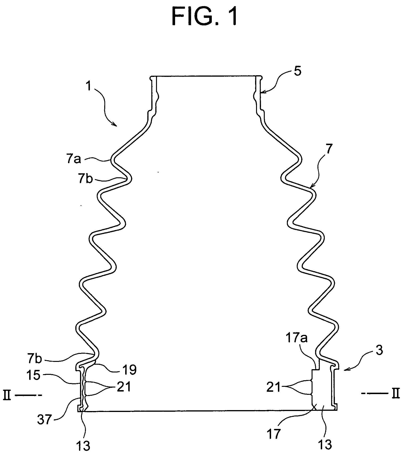
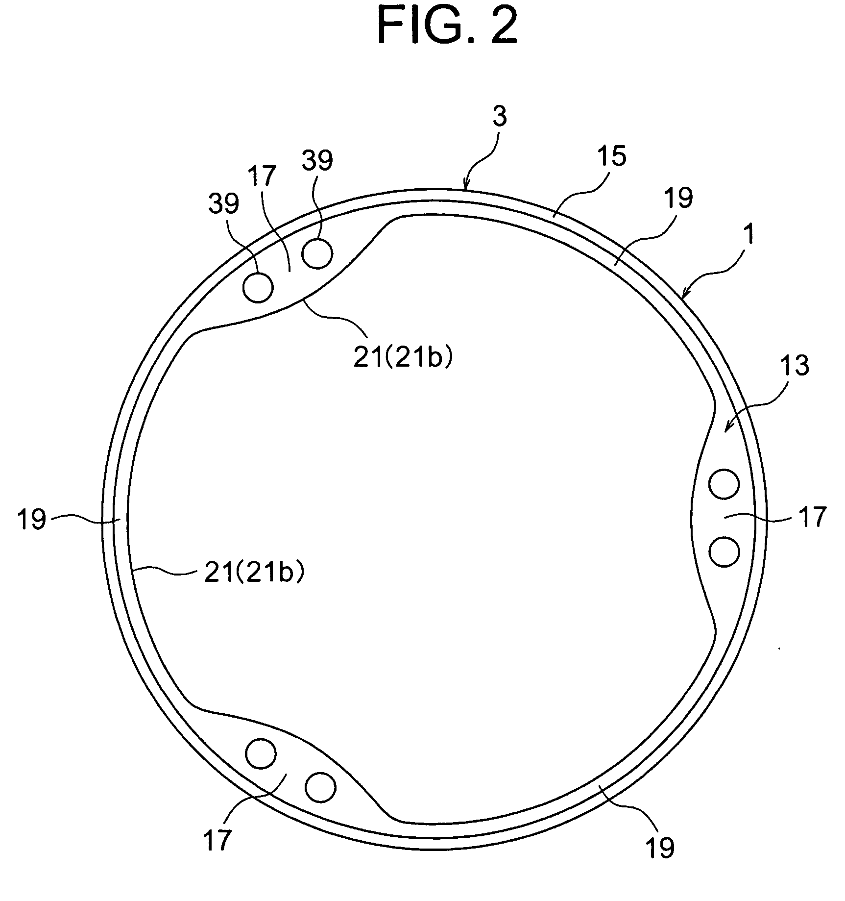
The present invention provides a boot for a constant-velocity universal joint that is compact, lightweight, and cost-effective. The boot has a primary molded member with a small-diameter side end portion and a large-diameter side end portion, and a secondary molded member with a thick portion that contacts the inner peripheral portion of the large-diameter side end portion. The secondary molded member is easily pulled out of the core mold and helps achieve a large rocking angle. The small-diameter portion just in the vicinity of the large-diameter side end portion can be effectively bent, and the whole boot can be downsized and lightened. The method of manufacturing the secondary molded member includes positioning a molten material injection point and applying pressure to the molten material to form the thick portion.

Problems solved by technology

Since the shifting causes grease leakage, an assembly operation becomes intricate in order to prevent the shifting.
Even in this case, unless the operation is carefully performed, the bellows large-diameter side end portion and the grommet shift from each other, and there is a possibility that the grease leaks.
Therefore, even when they are apparently integrated, they are not firmly fusion-bonded to each other, the apparently integrated place peels, and, as a result, a disadvantage such as a grease leakage is caused.
Accordingly, disadvantages of the above-described prior arts, such as operation intricacy and grease leakage have been solved (Japanese Patent Application No. 2003-041317).
Moreover, the present inventors have further found a problem in the newly developed inventive useful technique.
However, when the end portion of the thick portion is positioned in the vicinity of the bellows portion on the inner surface of the small-diameter portion, flexing properties of the small-diameter portion (referred to also as the valley portion) just in the vicinity of the large-diameter side end portion in the bellows portion are impaired.
However, since the undercut portion is easily caught by the core mold, the boot is pulled out by so-called forcible extraction.

Method used


Image

  • Method of manufacturing boot for constant-velocity universal joint and manufacturing apparatus for use in the method, and boot for constant velocity universal joint
  • Method of manufacturing boot for constant-velocity universal joint and manufacturing apparatus for use in the method, and boot for constant velocity universal joint
  • Method of manufacturing boot for constant-velocity universal joint and manufacturing apparatus for use in the method, and boot for constant velocity universal joint

Examples


example 1

[0083]“Primary Molding Step”

[0084] As a method of molding the primary molded member constituted of the large-diameter side end portion 3, small-diameter side end portion 5, and bellows portion 7, blow molding, injection blow molding and the like are well known, but the method is not especially limited, and an optimum molding method is appropriately applied to the scope of the present invention.

[0085]“Secondary Molding Step”

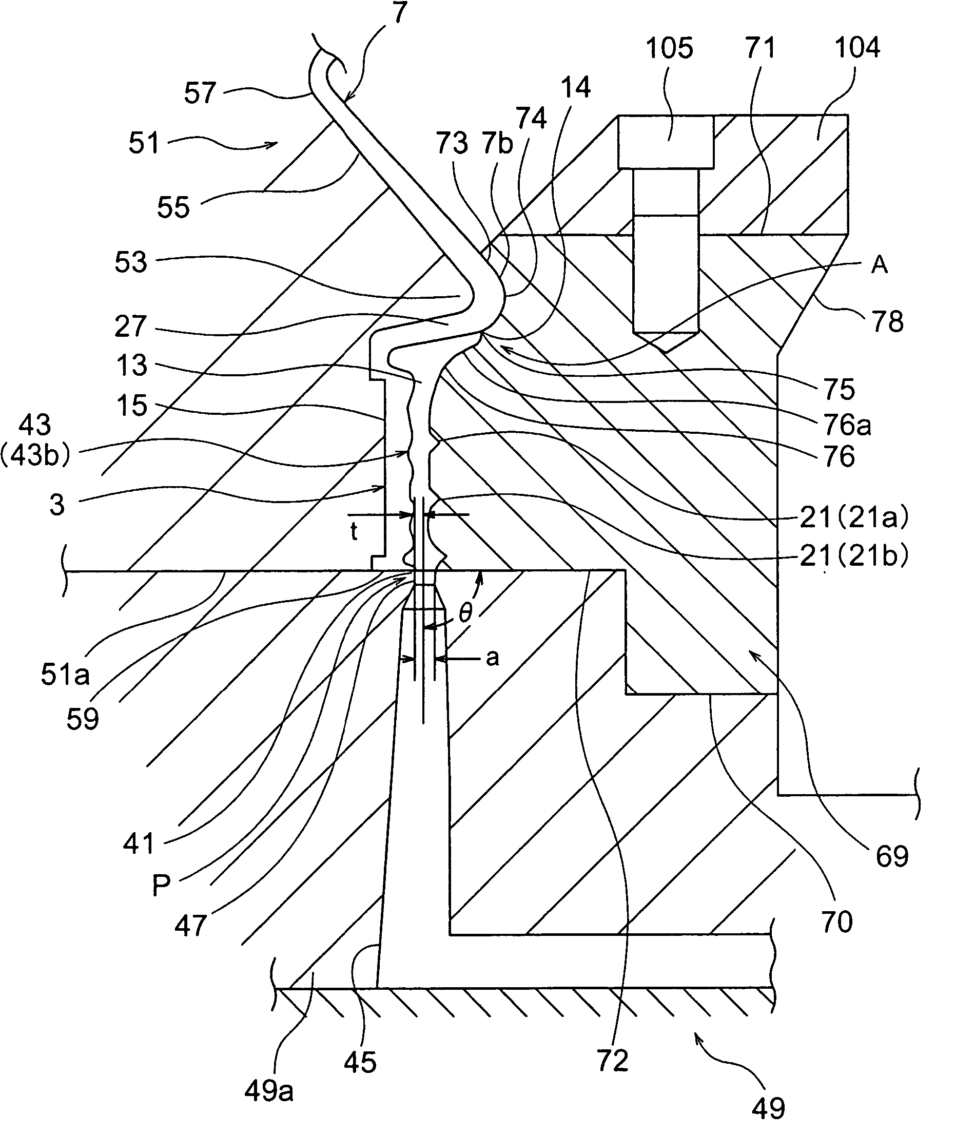
[0086] The present step will be described with reference to FIGS. 5A to 8. In the present step, the core mold 69 is inserted into the primary molded member molded in primary molding, and is held in the mold 49 for injection molding, a desired molten material is injected into the mold 49 at a high speed, and the secondary molded member 13 is integrally molded between the inner surface of the outer peripheral surface 15 of the large-diameter side end portion 3 of the primary molded member and the outer surface of the core mold 69. It is to be noted that since a kno...

example 2

[0165]FIGS. 13 and 14 show another example of the secondary molding step. It is to be noted that in the present example, as described later, only the formed place of the secondary molding space 43c, the injection position of the molten material and the like differ from those of the secondary molding space 43 of Example 1. The description of Example 1 applies to constitutions and functions / effects other than those described hereinafter, and the description is omitted.

[0166]“Primary Molding Step”

[0167] The basic constitution, molding method and the like of the primary molded member of the present example are similar to those of Example 1, but the large-diameter side end portion 3 is formed in a cylindrical shape having a straight sectional thickness. It is to be noted that unlike the present example, to enhance the adhesion to the secondary molded member, the outer peripheral surface 15 of the large-diameter side end portion 3 may also be formed in a coarse surface (concave / convex su...

example 3

[0199]FIGS. 16 and 17 show another example of the secondary molding step. It is to be noted that in the present example, as described later, only the formed places of the secondary molding spaces 43d, 43e, the injection position of the molten material and the like differ. The descriptions of Examples 1 and 2 apply to constitutions and functions / effects other than those described hereinafter, and description is omitted. Since the primary molding step is similar to that of Example 2, the secondary molding step will be described.

[0200]“Secondary Molding Step”

[0201] In the present example, secondary molding spaces 43d, 43e are formed between the core mold outer peripheral surface and the mold inner peripheral surface 50 via the inner / outer peripheral surface of the large-diameter side end portion 3, and the molten material is injected into the secondary molding spaces 43d, 43e to integrally mold the portion having different thicknesses which is the secondary molded member. The constitu...


PUM

PropertyMeasurementUnit
temperatureaaaaaaaaaa
diameteraaaaaaaaaa
velocityaaaaaaaaaa

Abstract

There is disclosed a boot for a constant-velocity universal joint, in which a secondary molded portion including a thick portion is formed in a large-diameter side end portion of a primary molded member, and the boot is easily pulled out of a core mold. The boot is downsized and lightened to reduce costs. A manufacturing method includes: a step of forming a secondary molding space 43 between an inner peripheral surface of a large-diameter side end portion 3 of the primary molded member and an outer peripheral surface of a core mold 69; a step of injecting a molten material into the secondary molding space to mold the secondary molded portion; and a step of integrally molding a secondary molded member on the inner peripheral surface of the large-diameter side end portion of the primary molded member to form a boot 1, moving a removable portion 83 of a second mold section 79 of the core mold 69 which abuts on at least the end portion of the thick portion in the vicinity of the bellows portion in a central axial direction of the core mold to remove the removable portion from an undercut portion 17a of a thick portion 17 just before separating the boot from the core mold, and separating the core mold 69 from the boot 1 in this state.

Description

BACKGROUND OF THE INVENTION [0001] 1. Field of the Invention [0002] The present invention relates to a boot for a constant-velocity universal joint, including a large-diameter side end portion attached to an outer peripheral surface of a tripod joint whose outer peripheral surface is formed to be concave and in which a plurality of axial-direction grooves are formed among constant-velocity universal joints for use, for example, in driving shafts for transmitting powers to hubs to which tires are attached from differential gears connected to engines of cars. [0003] 2. Description of the Related Art [0004] Constant-velocity universal joints are used, for example, in opposite end portions of a driving shaft for a car. Moreover, a flexible boot is attached to cover a bent portion of the constant-velocity universal joint in order to seal grease for lubricating the constant-velocity universal joint and to prevent invasion of foreign matters such as dust and water from the outside. A large...

Claims


Application Information

Patent Timeline
Patent Type & Authority Applications(United States)
IPC IPC(8): B29C45/00F16J15/52B29C45/14B29C45/16B29C45/44B29C49/04B29L31/24F16C11/06F16D3/205F16D3/84F16J3/04
CPCB29C45/0046B29C45/14336B29C45/14418B29C45/4421F16J3/041B29C2045/14934B29L2031/703F16D3/845B29C49/04F16D2250/0007F16D3/2055F16C11/06
Inventor SUEOKA, KAZUHIKOTAKADA, YASUJI
Owner FUKOKU CO LTD
Learn More