
Spread spectrum communication system receiving device

a communication system and spread spectrum technology, applied in the direction of radio transmission, electrical equipment, transmission, etc., can solve the problems of inability to configure a device at low cost, interference characteristics are important problems, and the means of detecting interference signals, so as to facilitate the ic implementation of the device, eliminate the single-frequency and narrow-band noise in the received signal, and improve the communication quality of spread spectrum communication

Inactive Publication Date: 2005-03-03
GCOMM
View PDF6 Cites 11 Cited by
  • Summary
  • Abstract
  • Description
  • Claims
  • Application Information

AI Technical Summary

Benefits of technology

An object of the present invention is to provide a spread spectrum system communication device capable of eliminating all of plural narrow-band interference signals in communication.
According to the aforementioned configuration, an interference signal (narrow-band interference signal) is detected and eliminated in a state in which a received signal is subjected to fast Fourier transform processing to be transformed to a frequency spectrum, and then by subjecting the received signal to inverse fast Fourier transform processing, the received signal from which the interference signal is eliminated can be obtained, whereby a spread spectrum communication system receiving device capable of eliminating plural narrow-band interferences can be provided. Accordingly, single-frequency and narrow-band noise in the received signal can be eliminated, which leads to an improvement in the communication quality of spread spectrum communication.
Moreover, the interference signal is detected and eliminated by digital processing, which makes it possible to facilitate the IC implementation of the device, and consequently, a low-cost spread spectrum communication system receiving device with a stable performance can be provided.

Problems solved by technology

However, in the case of a weak radio wave which does not have a frequency band provided for a specific communication service such as a cellular phone, interference characteristics are an important problem.
However, in arts described in these documents, a means for detecting the interference signal is complicated, which makes it impossible to configure a device at low cost.
Moreover, when there are plural narrow-band or single-frequency interference signals whose frequencies are apart from one another, it is impossible to eliminate all of the interference signals.

Method used


Image

  • Spread spectrum communication system receiving device
  • Spread spectrum communication system receiving device
  • Spread spectrum communication system receiving device

Examples


Embodiment Construction

Hereinafter, an embodiment of the present invention will be described based on the drawings.

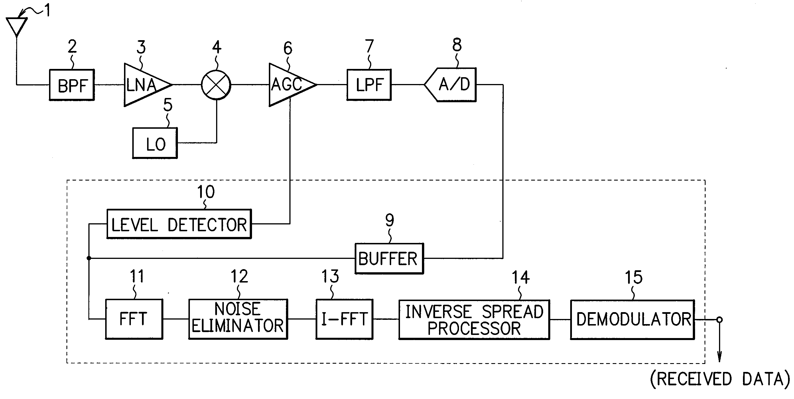
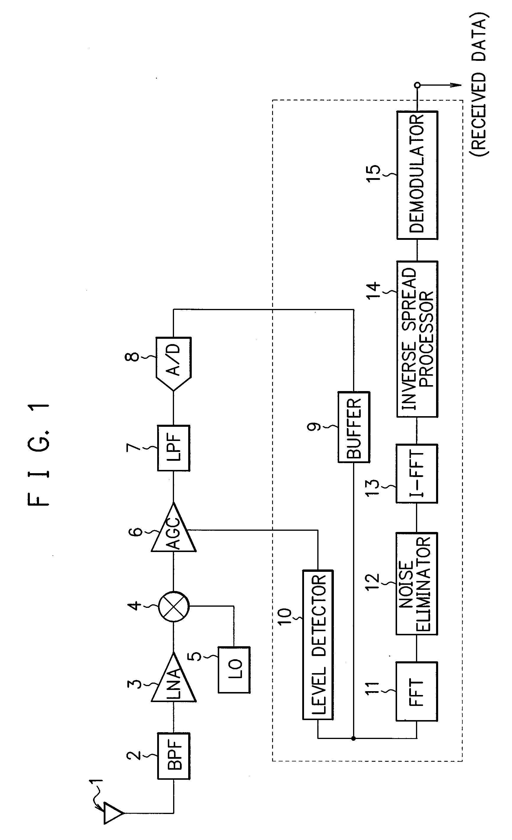
FIG. 1 is a block diagram showing an example of the configuration of a spread spectrum system communication device, and more specifically, receiving device according to the embodiment of the present invention.

A high-frequency received signal received by an antenna 1 in the spread spectrum system receiving device shown in FIG. 1 is inputted from the antenna 1 to a band-pass filter (BPF) 2, and its unnecessary frequency band is eliminated by the band-pass filter 2. Thereafter, the high-frequency received signal is amplified by a low-noise amplifier (LNA) 3.

A mixer 4 performs frequency conversion by mixing the high-frequency received signal amplified by the low-noise amplifier 3 with an output from a local oscillator (LO) 5. In this embodiment, a direct conversion system is shown as an example. Hence, an output frequency (frequency of an output signal) of the local oscillator 5 is equal to...


PUM


Abstract

A received signal whose frequency band is spread in a spread spectrum system is subjected to fast Fourier transform processing to be transformed to a frequency spectrum, based on this frequency spectrum, a narrow-band interference signal is detected and eliminated, and then by subjecting the received signal to inverse FFT, the received signal from which the interference signal is eliminated is obtained, whereby the narrow-band interference signal can be eliminated from the received signal by a simple configuration.

Description

CROSS REFERENCE TO RELATED APPLICATIONS This application is based upon and claims the benefit of priority from the prior Japanese Patent Application No. 2003-347565, filed on Sep. 1, 2003, the entire contents of which are incorporated herein by reference. BACKGROUND OF THE INVENTION 1. Field of the Invention The present invention relates to elimination of a narrow-band interference signal in a spread spectrum system communication device. 2. Description of the Related Art In spread spectrum communication, communication is performed by spreading a transmitted signal over a much wider frequency band than a frequency band of the transmitted signal. The spread spectrum communication is, in principle, excellent in fading characteristic and capable of high-speed communication, whereby, in recent years, its application field has been expanding, including a cellular phone and a wireless LAN. It is expected that the application field of radio communication will further expand by adoptin...

Claims


Application Information

Patent Timeline
IPC IPC(8): H04B1/707H04B1/10H04B1/71H04B7/216H04L27/30
CPCH04B1/7102H04B7/216H04L27/30
Inventor SAKAUE, MIKIOTOMISHIMA, HIDENORI
Owner GCOMM
Learn More